T5 Flare Gas Transducer Installation Guide 45
Chapter 3. Installing the Transducer Assemblies
3.6 Aligning the Transducers (Extended Velocity Range) (cont.)
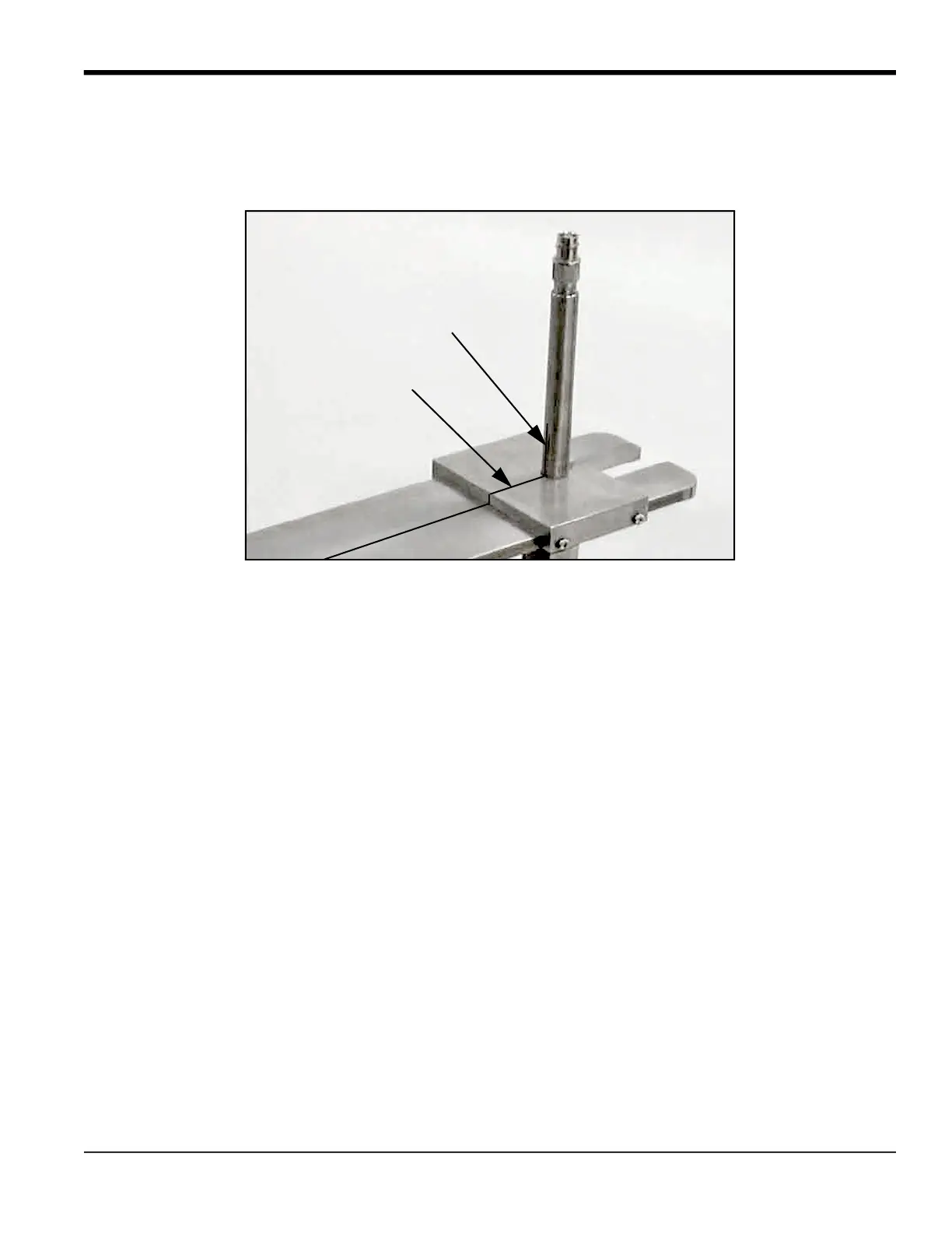
6. Check to see if the line on the upstream transducer tube is aligned with the line on the cover plate. If they are not
aligned, loosen the nuts on top of the barrel flange and rotate the transducer assembly until the two lines are
aligned (see
Figure 13
below). Then, re-tighten the nuts.
Figure 13: Upstream Transducer Mark Aligned with Cover Plate Line
7. Upon completion of the above steps, remove the cover plate, locking collar and guide plate from the transducer
assemblies.
8. Place the remaining bolts into the flanges and tighten them securely.
9. Place a tag on each isolation valve stating the following:
DO NOT OPERATE (CLOSE) WHEN
TRANSDUCER IS INSERTED INTO PIPE.
10. Refer to your flowmeter
Startup Guide
to make the transducer electrical connections.
Upstream
Transducer
Upstream Transducer Line
Cover Plate Line
 Loading...