41
Operating
Instructions
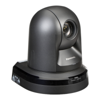
Parts and their functions
(continued)
i LAN connector for IP control [LINK/ACT]
This LAN connector (RJ-45) is connected when exercising
IP control over the unit from an external device.
Use a cable with the following specifications for the
connection to the LAN connector:
When connecting through a hub:
LAN cable* (category 5 or above),
max. 100 meters [328 ft]
When using a PoE+ compatible hub:
LAN cable* (category 5e or above),
max. 100 meters [328 ft]
When a hub is not used:
LAN cable* (category 5 or above),
max. 100 meters [328 ft]
*: Use of an STP (shielded twisted pair) cable is
recommended.
j Anti-theft wire mounting hole
Use this hole to attach the wire bracket (commercially
available).
k Audio input connector [AUDIO IN]
Inputs external audio (microphone, line).
l RS-232C connectors [RS-232C IN/OUT]
Connect to RS-232C cables.
RS-232C IN/OUT
connector
1 2
3
4
5
6
7
8
● Mini DIN 8-pin
(JST)
RS-232C IN RS-232C OUT
Pin
No.
Signal
Pin
No.
Signal
1 DTR_IN 1 DTR_OUT
2 DSR_IN 2 DSR_OUT
3 TXD_IN 3 TXD_OUT
4 GND 4 GND
5 RXD_IN 5 RXD_OUT
6 GND 6 GND
7 IR OUT R 7 NC
8 IR OUT L 8 NC
● Be aware that the polarities (+/−) of the serial data
may be different depending on the specifications of
the device to be connected.
Note
m DC IN connector [12V IN ]
Connect the AC adaptor supplied with the unit to this
connector to supply the DC 12 V voltage to the unit.
n Cable clamp
This is used to hold the cable connection to the DC IN
connector and prevent it from becoming disconnected.
o Ground connector
Connects to the ground connector on a wall outlet, ground
bar, etc. for grounding. (page 25)
p RS-422 connector [RS-422]
This RS-422 connector (RJ-45) is connected when
exercising serial control over the unit from an external
device.
Use a cable with the following specifications for the
connection to this connector.
The tally lamp can be lit by shorting the TALLY signal (pin
2) with GND (pin 1).
● Do not apply a voltage to the TALLY signal pin.
Note
LAN cable* (category 5 or above, straight cable), max.
1000 meters [3280 ft]
*: Use of an STP (shielded twisted pair) cable is
recommended.
2 4 6 8
Pin
No.
Signal
Pin
No.
Signal
1 GND 5 TXD +
2 TALLY 6 RXD +
3 RXD – 7 —
4 TXD – 8 —
q USB port
The unit can be used as a Web camera by connecting the
unit and a personal computer with USB Video Class.
r microSD card slot
The video and audio of the camera can be recorded to a
microSD card in MP4 format.
s Threaded hole (thread: 1/4-20UNC, ISO1222
[6.35 mm]) for mounting the camera
Use this hole when mounting the camera on a tripod, etc.
t HDMI connector [HDMI]
This is the HDMI video signal output connector.
 Loading...