40
Parts and their functions
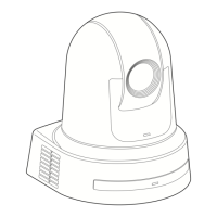
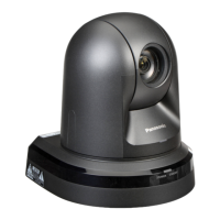
■Camera unit
<Rear panel>
<Bottom panel>
a Mount bracket for installation surface
(supplied accessory)
Mount this bracket onto the installation surface, and then
attach the camera main unit to the bracket.
b Drop-prevention wire
Pull out the wire from the bottom panel of the camera
main unit, and attach it to the hook of the mount bracket.
c Hole for securing the camera pedestal
This hole is provided in the bottom panel of the camera
pedestal.
d Wireless remote control signal light-sensing
area
Light sensors are located in four places; at the front of the
camera pedestal and on either side.
e Status display lamp
This lights in the following way depending on the status of
the unit.
Orange: When the standby status is established
Green: When the power is on
Red: When trouble has occurred in the unit
Green and blinks twice:
When a signal matched by the remote control
ID has been received from the wireless remote
control (optional accessory) while the power is
on
Orange and blinks twice:
When a signal which is not matched by the
remote control ID has been received from the
wireless remote control (optional accessory)
while the power is on
f Camera head
This rotates in the horizontal direction.
g Lens unit
This rotates in the up and down direction.
h Tally lamp
This comes on or goes off in response to the control from
the controller but only when “On” has been selected as the
tally lamp use setting.
 Loading...