37 (E)
Control interface for external devices
TALLY/GPI
TALLY IN 1 to TALLY IN 5 are contact input ports which are used to light the unit’s
tally indicators (above the CAMERA STATUS/SELECTION buttons).
The tally lamps light with contact input.
GPI IN 1 to GPI IN 4 are contact input ports which are used to control the unit from
an external source.
GPI OUT 1 to GPI OUT 4 are open output ports which are used to output the
statuses to an external source.
(D-sub 15-pin, female, inch thread)
81
15
9
Pin No. Signal Description of signal Operation
1 TALLY IN 1 CAM1 tally input
Contact input
9 TALLY IN 2 CAM2 tally input
2 TALLY IN 3 CAM3 tally input
10 TALLY IN 4 CAM4 tally input
3 TALLY IN 5 CAM5 tally input
11 GND Ground
4 GPI IN 1 Preset input 1
Contact input
12 GPI IN 2 Preset input 2
5 GPI IN 3 Preset input 3
13 GPI IN 4 Panel lock
6 GPI OUT 1
Remote camera selection 0
Open collector output
14 GPI OUT 2
Remote camera selection 1
7 GPI OUT 3
Remote camera selection 2
15 GPI OUT 4 Alarm
8 NC Not used
GND
GPI OUT
LED
Example of GPI OUT connections
Ensure that the conditions given below are satisfied.
Dielectric strength: Max. DC 24 V
Current: Max. 50 mA
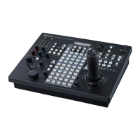
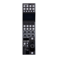
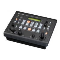
AW-RP50
(Max. voltage: 24 V)
(Max. current: 50 mA)
GND
GPI IN
TALLY IN
+3.3 V
Example of TALLY IN and GPI IN connections
Provide contact inputs.
AW-RP50
: The selection statuses (CAMERA STATUS/SELECTION buttons 1 to 5) of the remote cameras can be monitored at
GPI OUT 1 to GPI OUT 3.
CAMERA STATUS/SELECTION
button
Remote camera
selection 0
(GPI OUT 1)
Remote camera
selection 1
(GPI OUT 2)
Remote camera
selection 2
(GPI OUT 3)
1 On Off Off
2 Off On Off
3 OnOnOff
4 Off Off On
5 On Off On
 Loading...