Operating Instructions
Parts and their functions
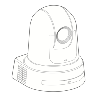
Camera unit
RS-422
IR ID
3G SDI OUT
G/L IN
AUDIO IN
LAN
LINK ACT
DC IN 12V
SERVICE
1
2
4
3
5
8
6
9
7
21
10 611 1512 13
201917 1816
14
7
Rear panel
Bottom panel
1. Mount bracket for installation surface (supplied
accessory)
Mount this bracket onto the installation surface, and then attach the
camera main unit to the bracket.
2. Drop-prevention wire
This wire is screwed down to the bottom panel of the camera main
unit. Loop the circle part of the wire around the hook of the mount
bracket.
3. Status display lamp
This lights in the following way depending on the status of the unit.
Orange Light up When the standby status is established
Blink twice When a signal not matched by the remote control
ID has been received from the wireless remote
control (optional accessory) while the power is on
Green Light up When the power is on
Blink twice When a signal matched by the remote control
ID has been received from the wireless remote
control (optional accessory) while the power is on
Blinking
rapidly
When the initialization process is complete
Red Light up When trouble has occurred in the unit
Blinking
slowly
Firmware being updated
Blinking
rapidly
When a PoE++ software authentication error has
occurred
4. Ventilation holes
Blocking the ventilation holes may cause a malfunction. Make sure
there is sufficient space around the ventilation holes.
5. Pan head
This rotates in the right and left direction.
6. Wireless remote control signal light-sensing area
There are three light-sensing areas on the front and rear panels of the
camera pedestal.
7. Hole for securing the camera pedestal
This hole is provided in the bottom panel of the camera pedestal.
8. Camera head
This rotates in the up and down direction.
9. Tally lamp
This comes on or goes off in response to the control from the controller
but only when “On” has been selected as the tally lamp use setting.
The tally lamp is red or green.
Red Light up When receiving a red tally signal
Blink once When a Pan/Tilt limit is set
Blink twice When the Pan/Tilt limit is canceled
Blink three
times
When start up of this unit is complete
Green Light up When receiving a green tally signal
46 47
 Loading...