Installation Instructions
Before installation
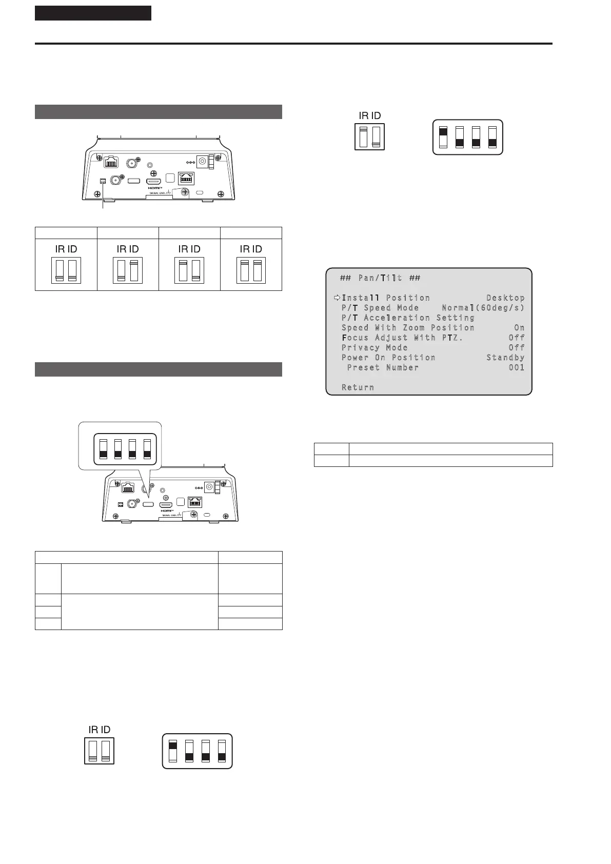
Be sure to configure the switches on the connector panel and bottom of
the unit before installing it.
Configuring the switches after the unit is installed may prove difficult.
IR ID switch settings
The IR ID switches are located on the connector panel of the unit.
RS-422
IR ID
3G SDI OUT
G/L IN
AUDIO IN
LAN
LINK ACT
DC IN 12V
SERVICE
IR ID switch
CAM1 CAM2 CAM3 CAM4
These are used to select the ID of the wireless remote control (optional
accessory). (→ page 56)
The IR ID switch settings “CAM1” to “CAM4” correspond to the
CAMERA <1> to <4> buttons on the wireless remote control.
Service switch settings
The service switches are located on the connector panel of the unit.
Perform switch settings before turning the unit on.
RS-422
IR ID
3G SDI OUT
G/L IN
AUDIO IN
LAN
LINK ACT
DC IN 12V
SERVICE
SW1
ON
OFF
SW2 SW3 SW4
Service switch
Function Factory settings
SW1 Switches for initialization
(Refer to the explanations in “Initialization 1”
and “Initialization 2”)
OFF
SW2
Always leave at OFF (used for factory
adjustments)
OFF
SW3 OFF
SW4 OFF
Initialization 1
• Reset the user authentication settings and host authentication settings
for network connection.
(This will delete all the registered user information (IDs/passwords)
and host information (IP addresses).)
• With the IR ID switches and service switches set as shown below, turn
on the power of the unit.
SW1
ON
OFF
SW2 SW3 SW4
<NOTE>
When initialization is complete, the status display lamp on the front of
the unit blinks green. Set the service switches back to their original
positions (SW1 to SW4 all OFF), then restart the unit.
Initialization 2
• The unit is reset to the state it was in at the time of purchase. (All
camera menu setting values and network setting values are reset.)
• With the IR ID switches and service switches set as shown below, turn
on the power of the unit.
SW1
ON
OFF
SW2 SW3 SW4
<NOTE>
• When initialization is complete, the status display lamp on the front
of the unit blinks green. Set the service switches back to their original
positions (SW1 to SW4 all OFF), then restart the unit.
Setting the installation method (“Desktop” or
“Hanging”) from the OSD menu
Set “Desktop” or “Hanging” in [Install Position] on the [Pan/Tilt] screen
from the OSD menu of this unit.
Pan/Tilt
Install Position Desktop
P/T Speed Mode Normal(60deg/s)
P/T Acceleration Setting
Speed With Zoom Position On
Focus Adjust With PTZ. Off
Privacy Mode Off
Power On Position Standby
Preset Number 001
Return
Install Position [Desktop, Hanging]
[Desktop] or [Hanging] is selected here as the method used to install
the unit.
Desktop Stand-alone installation
Hanging Suspended installation
<NOTE>
• When [Hanging] has been selected, the top, bottom, left and right
of the images will be reversed, and up/down/left/right control for
panning and tilting will also be reversed.
8
 Loading...