71
15.2.16 F90 (Power Factor Correction (PFC) Circuit Protection)
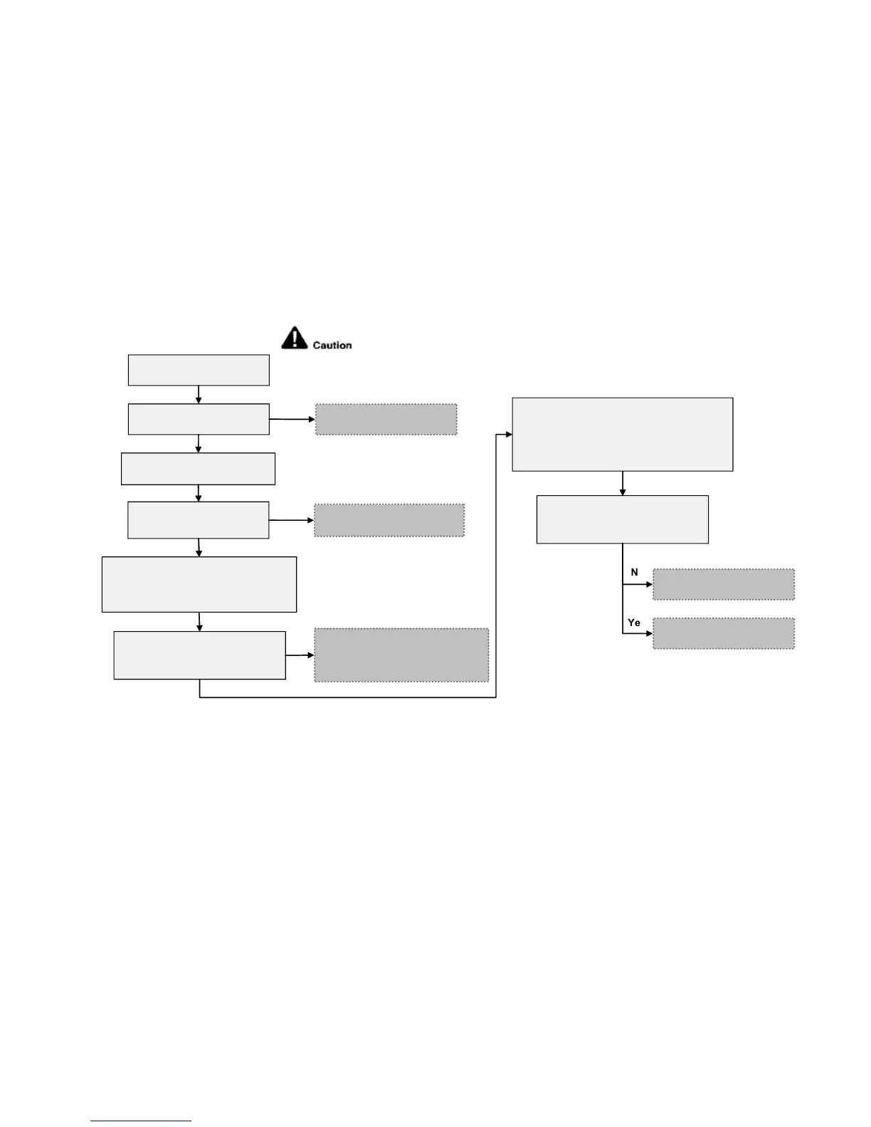
Malfunction Decision Conditions
During startup and operation of cooling and heating, when PFC protection circuitry at the outdoor unit main PCB
senses low DC voltage level (below 280Vdc).
Malfunction Caused
Low DC voltage due to power supply drop.
Low DC voltage due to compressor windings not uniform.
Reactor connection is disconnected.
Faulty outdoor unit PCB.
Abnormality Judgment:
4 times happen within 20 minutes.
Troubleshooting
Check the supply voltage
Correct the power supply.
No
Supply voltage as
specified?
Operate the system. Verify PFC
abnormality by measuring DC voltage
between P1 (red) and N1 (black)
terminal at the outdoor inverter PCB.
- Defect in DC supply/PFC circuitry
- Replace the DB/SPM PCB /
Inverter PCB
No
Is the DC voltage between P1
(red) and N1 (black) terminal
normal (between 285-315Vdc)?
No
Yes
Check the compressor winding resistance:
- Turn off the power supply and
disconnect the harnesses U, V, and W
- Measure the winding resistance between
U-V, V-W, and W-U
Yes
For safety reason and to prevent component
breakdown, always switch off the power before
remove and connect the component.
Are the compressor’s winding
resistance (U-V, V-W, U-W)
uniform?
Replace the compressor.
Replace the outdoor unit
PCB.
Yes
Check the reactor
connection
- Connector disconnected
- Correct the connection
No
Is the reactor connector
connection ok?
Yes