5-22
5
4. Mini VRF System Alarm Codes
Mini VRF SYSTEM
Trouble Diagnosis
1-1
1-4 : Single-phase model
1-2 : 3-phase model
3-1 : Single-phase model
2-1 : 3-phase model
Check for open circuit and the voltage at the breaker.
if a problem is found, fix it and check again.
Yes
No
Turn the power back on and check again.
Is the alarm triggered again?
1-4
2-1
Power wiring N-phase is connected.
Power wiring L2 and N are reverse connected. (3-phase only)
The connector CN-RY on the outdoor CR PC board is
connected properly (locked). (3-phase only)
1-2
1-3
4-1
Yes
No
Correct wiring
1-3
Yes
No
Correct wiring
1-4
Yes
No
1 Check
the power
supply &
the wiring
Are the wires (RE1, RE2) from the reactor firmly installed?3-1
3-2
Correct wiring
Yes
No
Turn the power back on and check again.
Is the alarm triggered again?
3-2
Replace the outdoor
unit HIC PC board.
4-1
Yes
No
3 Check the
outdoor
unit HIC
PC board
2 Check the
outdoor
unit CR
PC board
There may be a instantaneous blackout failure.
If there is nothing abnormal, see what happens.
4-1
4 Final check
P05 AC Power Supply Trouble
Error Detection Method
Error Diagnosis
Instantaneous blackout
•
Note : The work involved in diagnosing each of the items is extremely dangerous, so turn the power off at the breaker before
performing the tests.
Zero-cross (waveform input of power supply) error
•
DC voltage charge failure
•
1.
2.
Is the voltage on each of the
terminal boards within
+
10%
of the rated voltage?
Correct wiring
(connector)
3-1Yes
No
P
U
V
W
NU
RE1
RE2
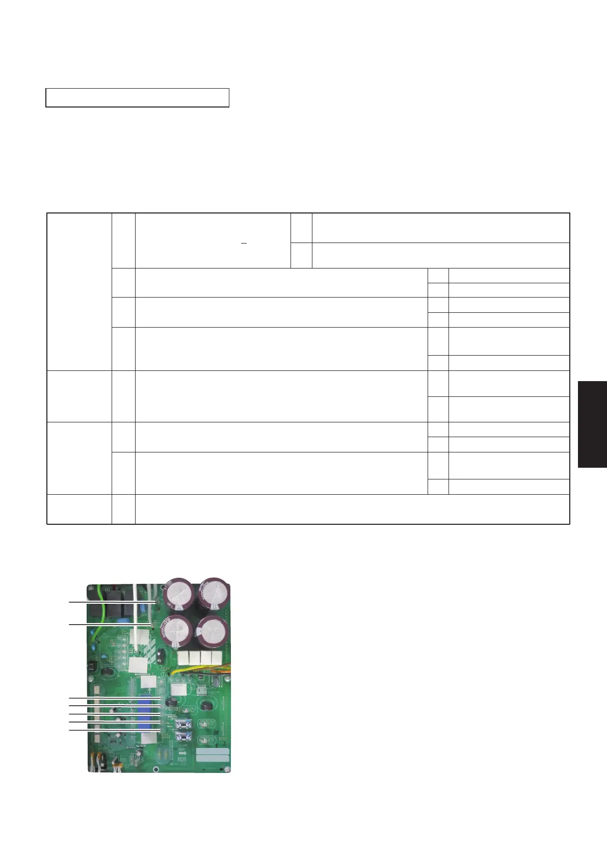
(3-phase outdoor unit HIC PC board)
ACXA73-3104* : (U-200PZH2E8, U-250PZH2E8)
■ Outdoor Unit Control HIC PCB
SM830281-00_欧州向け R32シングル TD&SM.indb 22 20/01/09 15:05:23