1-11-1-1-2
1
1-11. ELECTRICAL WIRING
General Precautions on Wiring
Indoor Units
1. Type E3
S-200PE3E5B, S-250PE3E5B
(1)
(4)
(5)
(6)
(7)
(8)
Before wiring, confirm the rated voltage of the unit as shown on its nameplate, then carry out the wiring closely following
the wiring diagram.
Check local electrical codes and regulations before wiring.
Also, check any specified instruction or limitations.
(2)
(3)
This equipment is strongly recommended to be installed with Earth Leakage Circuit Breaker (ELCB) or Residual Current
Device (RCD). Otherwise, it may cause electrical shock and fire in case of equipment breakdown or insulation breakdown.
Earth Leakage Circuit Breaker (ELCB) must be incorporated in the fixed wiring in accordance with the wiring regulations.
The Earth Leakage Circuit Breaker (ELCB) must be an approved 10-16 A, having a contact separation in all poles.
To prevent possible hazards from insulation failure, the unit must be grounded.
Each wiring connection must be done in accordance with the wiring system diagram.
Wrong wiring may cause the unit to misoperate or become damaged.
Do not allow wiring to touch the refrigerant tubing, compressor, or any moving parts of the fan.
Unauthorized changes in the internal wiring can be very dangerous. The manufacturer will accept no responsibility for any
damage or misoperation that occurs as a result of such unauthorized changes.
Regulations on wire diameters differ from locality to locality. For field wiring rules, please refer to your LOCAL ELECTRICAL
CODES before beginning.
You must ensure that installation complies with all relevant rules and regulations.
To prevent malfunction of the air conditioner caused by electrical noise, care must be taken when wiring as follows:
The remote control wiring and the inter-unit control wiring should be wired apart from the power supply wiring.
Use shielded wires for inter-unit control wiring between units and ground the shield on both sides.
Recommended Wire Length and Wire Diameter for Power Supply System
Indoor unit
(B) Power supply
Type
Time delay fuse or
circuit capacity
2.5 mm
2
E3 Max. 30 m 10-16 A
WARNING
CAUTION
Control wiring
(C) Inter-unit control wiring
(between outdoor and indoor units)
(D) Remote control wiring
0.75 mm
2
(AWG #18)
0.75 mm
2
(AWG #18)
Use shielded wiring*
Max. 500 m
Max. 1,000 m
NOTE
* With ring-type wire terminal.
The above descriptions can be used for the model
CZ-RTC4 or CZ-RTC5B. For other remote controllers,
refer to the manual of each unit.
NOTE
(1) See the “Recommended Wire Length and Wire
Diameter for Power Supply System” for the explanation
of “B”, “C” and “D” in the above diagram.
(2)
(3)
(4) Regarding R.C. address setting, refer to the installation
The basic connection diagram of the indoor unit shows
the terminal boards, so the terminal boards in your
equipment may differ from the diagram.
Refrigerant Circuit (R.C.) address should be set before
turning the power on.
instructions supplied with the outdoor unit. Auto address
setting can be executed by remote controller automatically.
Refer to the installation instructions supplied with the
remote controller (optional).
Ground
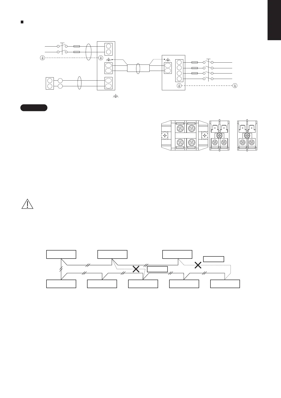
Wiring System Diagrams
Power supply
220-230-240V~ 50Hz
Power supply
380-400-415V 3N~ 50Hz
U2
U1
R2
R1
L
N
2
1
D
B
L
N
2
1
L1
L2
L3
N
C
L1
L2
L3
N
U2
U1
WHT
BLK
Ground
Remote controller
Indoor unit
Outdoor unit
(
: Functional earthing)
2P terminal board × 3
Power
supply
Remote
wiring
control
Inter-unit
wiring
control
L N U1 U2 R1 R2
(1) When linking the outdoor units in a network, disconnect the terminal extended from the short plug from all
outdoor units except any one of the outdoor units. (When shipping: In shorted condition.)
For a system without link (no wiring connection between outdoor units), do not remove the short plug.
(2) Do not install the inter-unit control wiring in a way that forms a loop.
Outdoor unit Outdoor unit Outdoor unit
Indoor unit Indoor unit Indoor unit Indoor unit
Prohibited
Prohibited
Indoor unit
CAUTION
SM830281-00_欧州向け R32シングル TD&SM.indb 2 20/01/09 14:59:30