22
2-2
OC
(CN040, blue)
EMG
(CN044,
brown)
Jumper
(JP040)
2-2. Precautions
Request that the customer be present when the test run is performed.
At this time, explain the operation manual and have the customer perform the actual steps.
Be sure to pass the manuals and warranty certificate to
the customer.
Check that the 220 – 240 VAC power is not connected
to the inter-unit control wiring connector terminal.
* If 220 – 240 VAC is accidentally applied, the indoor or
outdoor unit control PCB fuse will blow in order to
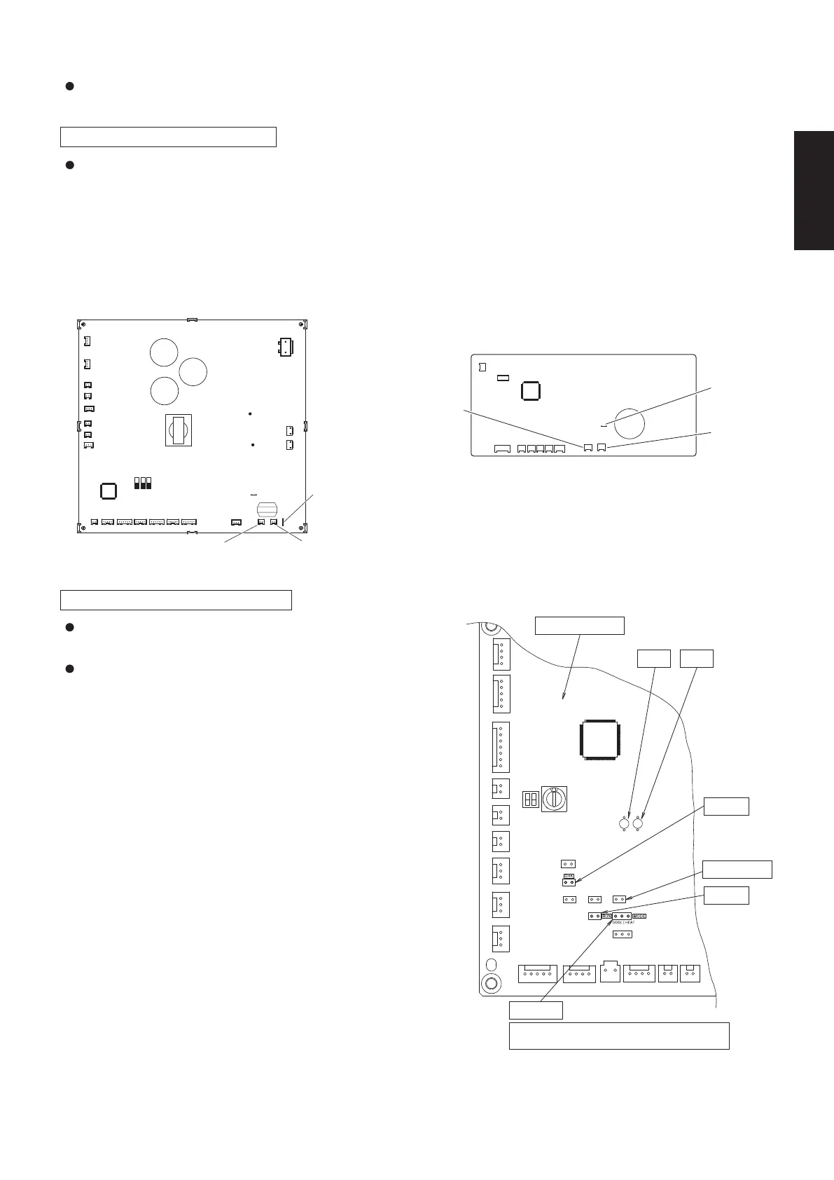
Fig. 2-4
Check that the 220 –240 VAC power is not connected to the inter-unit control wiring connector terminal.
If 220 –240 VAC is accidentally applied, the indoor unit control PCB fuse will blow in order to protect the PCB.
In this case, make the wiring correctly.
Then disconnect the 2P connectors (OC) that are connected to the indoor unit PCB, and replace them with
2P connectors (EMG).
If operation is still not possible after changing the brown connectors, cut the jumper on the indoor unit control
PCB.(Be sure to turn the power OFF before performing this work.)
protect the PCB.
Correct the wiring connections, then disconnect the 2P
Outdoor main PCB
connectors that are connected to the PCB, and replace
them with 2P connectors.
LED1 LED2
If operation is still not possible after changing the brown
connectors, try cutting the varistor.
(Be sure to turn the power OFF before performing
this work.)
Fig. 2-3
Type E3 Type U3
OUTDOOR UNIT MAIN PCB (CR)
INDOOR UNIT MAIN PCB (CR)
CHK pin
Outdoor main PCB
LED1
PUMPDOWN
RUN pin
MODE pin
mode.
*MODE pin: factory setting is cooling operation
LED2
EMG (CN044, brown) OC (CN040, blue)
(JP040)
Jumper
*
SM830281-00_欧州向け R32シングル TD&SM.indb 2 20/01/09 15:02:44