1-10-2
1
Precautions Regarding External Air Intake 1-10-1.
(1) Ventilation Load
Ensure that the design of the air conditioner takes air conditioning loads into consideration when external air intake is
involved.
(2) Restrictions on External Air Intake
Ensure that the design conforms to the restrictions on air intake volume stipulated in accordance with the model of
the indoor unit and the intake method. Consideration must also be taken to mixed air content listed in (3) below
without fail.
*If the air intake volume does not satisfy the required ventilation volume, air must be fed into the room separately with
the use of a total heat exchanger or a fresh air processing air conditioner, etc.
(3) Mixed Air
The amount of external air intake must be set within the scope of the unit’s usage conditions when external air and
internal air is mixed together. This is especially important in the following cases, in which it is necessary to either
feed external air into the room after it has been processed or reduce the amount of external air that is fed in.
1
When the external dew-point temperature is greater than the dry-bulb temperature of the air sucked into the unit
Ensure that processing is performed so that the external dew-point temperature is lower than the temperature of
the air sucked into the unit to prevent the risk of condensation building up.
2
In the case of low external temperatures
There are cases in which the temperature of mixed air is lower than the operating range of the unit if excessive
amounts of external air intake are used when the external temperature is low.
This problem is to be solved by either feeding external air into the room after it has been processed or reducing
the amount of external air that is fed in.
3
When used in combination with humidifiers
External air must always be processed when the external air temperature reaches freezing point to prevent the
risk of the humidifier freezing.
(4) Arranging Ducts and Filters in the Field
External air intake ducting must be arranged in the field.
External air filters must also be installed without fail in order to
prevent the intake of dust and grit.
(5) Thermal Insulation for Ducts
Ensure that all external air intake ducting is heat-insulated
without fail. Failure to observe this may result in the build-up
of condensation.
(6) External Air Intake Coupling
Ensure that the design for external air intake is coupled with
the fan blower operations of the indoor unit.
There are cases in which the dust that accumulates in the
filter is blown into the room if the external air is fed from the
filter. There are also cases in which the noise of external air
being fed into the room can be heard from the indoor unit if
external air is forcibly fed when the booster fan or other
components on the indoor unit are not operating.
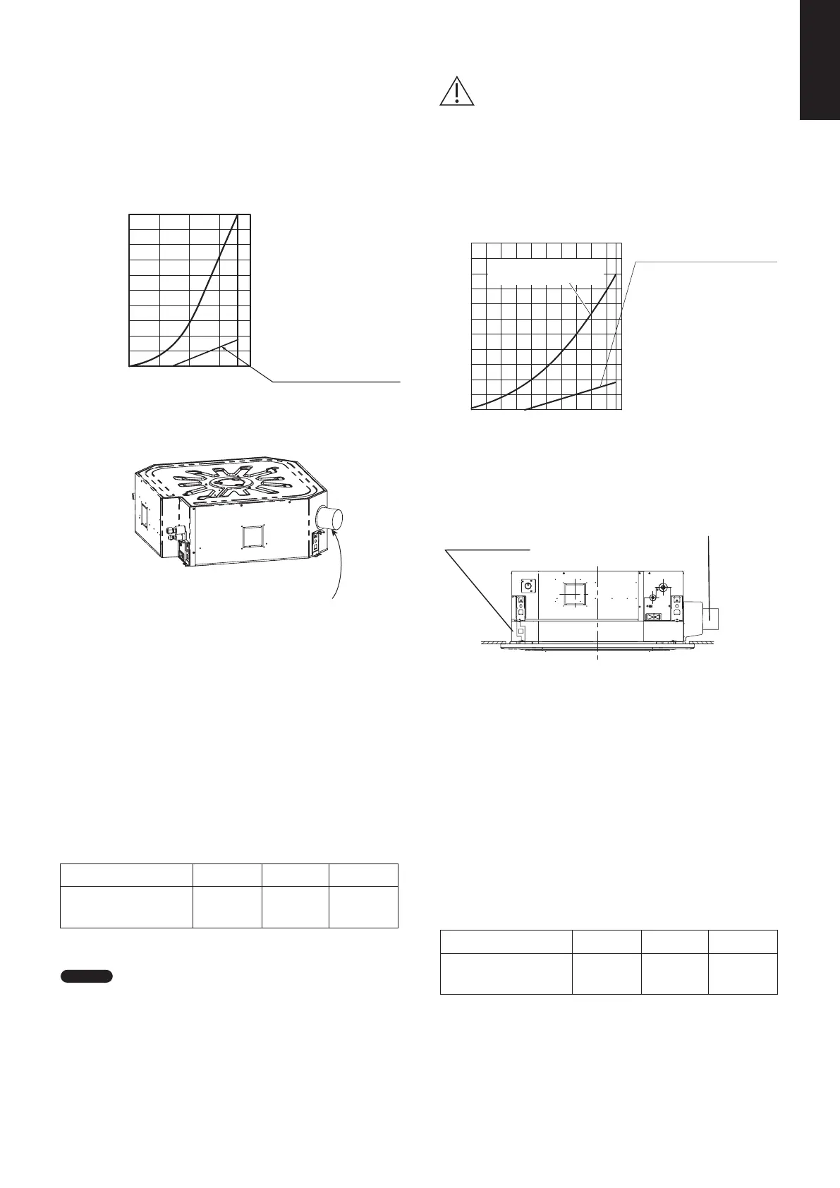
(7) Booster Fan Selection
Select the booster fan in accordance with the resistance of
the external air intake duct (diagram on the pressure loss
characteristics of the air flow volume for flexible cylindrical
ducts) and the resistance prevalent inside the unit (external
air intake volume & resistance within unit / operation noise
characteristics).
Regarding the installation direction of the external air intake
duct, refer to the Installation Instructions provided with the
external air intake duct.
(8) Attaching the External Air Intake Flange
ø100
ø150
ø125
Airflow (m
3
/h)
Pressure Loss (Pa)/Meter
Flexible Cylindrical Duct
Air Flow Volume for Flexible Cylindrical
Duct-Pressure Loss
30 50
100 200
400500
300
30
20
10
0.8
0.6
0.4
0.2
0.1
6
4
2
1
1-10. Fresh Air Intake
• 4-Way Cassette (Type U3)
When an External Air Intake Flange (ø100) is in Use
External Air Intake Volume and Resistance and
Operation Noise Characteristics within the Unit
• Calculate the operation noise when external air is being
fed by combining the noise when only external air is being
fed as shown in the graph for operation noise
characteristics and the operation noise of the unit as
stipulated in the catalogue.
• The operation noise conforms to JIS standards and
constitute measurements taken in an anechoic chamber
1.5 m directly beneath the indoor unit.
Under normal circumstances, the values shown here are
greater owing to the effects of surrounding noise and
reverberation when the unit is actually installed.
With the External Air Intake Flange Attached
Resistance within the Unit (Pa)
External Air Intake Volume (m
3
3
/h)
External Air Intake Volume (m /h)
Noise with only External
Air Intake dB(A)
Operation Noise
(External Air Intake Only)
0
0
10
20
30
20
30
40
50
40
50
60
70
80
90
100
5
10
15 2018
Type U3
1-10-2. External Air Intake Volume & Resistance
Within Unit / Operation Noise Characteristics
Resistance within the unit (Pa)
Noise with only External
Air Intake dB(A)
External Air Intake Volume & Resistance Within Unit/
Operation Noise Characteristics
With the External Air Intake Chamber Attached
Use the following diagram along with
the section "1-10-1. Precautions
Regarding External Air Intake".
In a Case of External Air Intake
Using Air Intake Chamber (CZ-FDU3+CZ-ATU2)
• Calculate the operation noise when external air is being
fed by combining the noise when only external air is being
fed as shown in the diagram for operation noise
characteristics and the operation noise of the unit as
stipulated in the catalogue.
• The operation noise conforms to JIS standards and
constitute measurements taken in an anechoic chamber
1.5m directly below the indoor unit. Under normal
circumstances, the diagram shown above is greater owing
to the effects of surrounding noise and reverberation when
the unit is actually installed.
100
90
80
70
60
50
40
30
20
10
0
-10
500
50
40
30
20
100 150 200 240
Resistance within the unit
(High speed wind)
Operation noise
(External air intake only)
Filter chamber
(CZ-FDU3)
Kit for external air intake (for chamber)
(CZ-ATU2)
Connection duct: diameter ø100
Duct (ø100) for Connecting
the External Air Intake Flange
CAUTION
The amount of external air that is possible to feed
when it is fed directly into the unit (ø100)
Type
S-3650PU3E S-6071PU3E S-1014PU3E
15
17 (60)*
* For S-6071PU3E (60) and S-6071PU3E (71), see the Combination
Table items 60 and 71
on page 12.
* For S-6071PU3E (60) and S-6071PU3E (71), see the Combination
Table items 60 and 71
on page 12.
18 (71)*
18
Permissible Air Intake
Volume (m³/h)
NOTE
The operation noise for models that use small units is lower,
so use values that are within the range shown in the above
table.
Using values that exceed these will result in noise when only
external air is fed being louder than the noise emitted from the
unit.
(CZ-FDU3+CZ-ATU2)
The amount of external air that is possible to feed
when external air intake chamber is in use
* The operation noise for models that use small units is
lower, so use values that are within the range shown in
the above table. Using values that exceed these will
result in noise when only e
.
xternal air is fed being louder
than the noise emitted from the unit.
Type
S-3650PU3E S-6071PU3E S-1014PU3E
180
190 (60)*
240 (71)*
240
Permissible air Intake
volume (m³/h)
SM830281-00_欧州向け R32シングル TD&SM.indb 2 20/01/09 14:59:30