1-11-2-1-3
1
The product meets the technical requirements of EN/IEC 61000-3-3.
Decide the length and size of the power supply cable based on the maximum ampere tabulated above in accordance with the national wiring regulations.
Select the fuse(s) and/or circuit breaker(s) from the types and ratings suitable for the maximum ampere tabulated above in accordance with the national wiring
regulations.
If capacity of power supply circuit and enforcement are not enough, it can causes the electric shock and a fire.
(1) When linking the outdoor units in a network, disconnect the terminal extended from the short plug from all outdoor units except any one of the
outdoor units. (When shipping: In shorted condition.)
For a system without link (no wiring connection between outdoor units), do not remove the short plug.
(2) Do not install the inter-unit control wiring in a way that forms a loop.
Outdoor unit Outdoor unit Outdoor unit
Indoor unit Indoor unit Indoor unit Indoor unit
Prohibited
Prohibited
Indoor unit
(3) Do not install inter-unit control wiring such as star branch wiring. Star branch wiring causes mis-address setting.
Outdoor unit
Indoor unit
Indoor unit
Indoor unitIndoor unit
NO
Branch point
(4) If branching the inter-unit control wiring, the number of branch points should be 16 or fewer.
Outdoor unit
Outdoor unit
Outdoor unit
: Branch point
Indoor unit
Indoor unit Indoor unit
Indoor unitIndoor unit
Indoor unit
Indoor unit
More than 2m required
Central Controller
(5) Use shielded wires for inter-unit control wiring and ground the shield on both sides,
otherwise misoperation from noise may occur. Connect wiring as shown in Section
“ Wiring System Diagrams” on page 1-11-1-1-2, 1-11-1-2-2.
(6) Use the standard power supply cables for Europe (such as H05RN-F or H07RN-F which conform to CENELEC (HAR) rating specifications) or use the
cables based on IEC standard. (60245 IEC57, 60245 IEC66)
WARNING
Loose wiring may cause the terminal to overheat or result in unit malfunction. A fire hazard may also occur.
Therefore, ensure that all wiring is tightly connected.
When connecting each power wire to the terminal, follow the instructions on “How to connect wiring to the terminal” and fasten the wire
securely with the terminal screw.
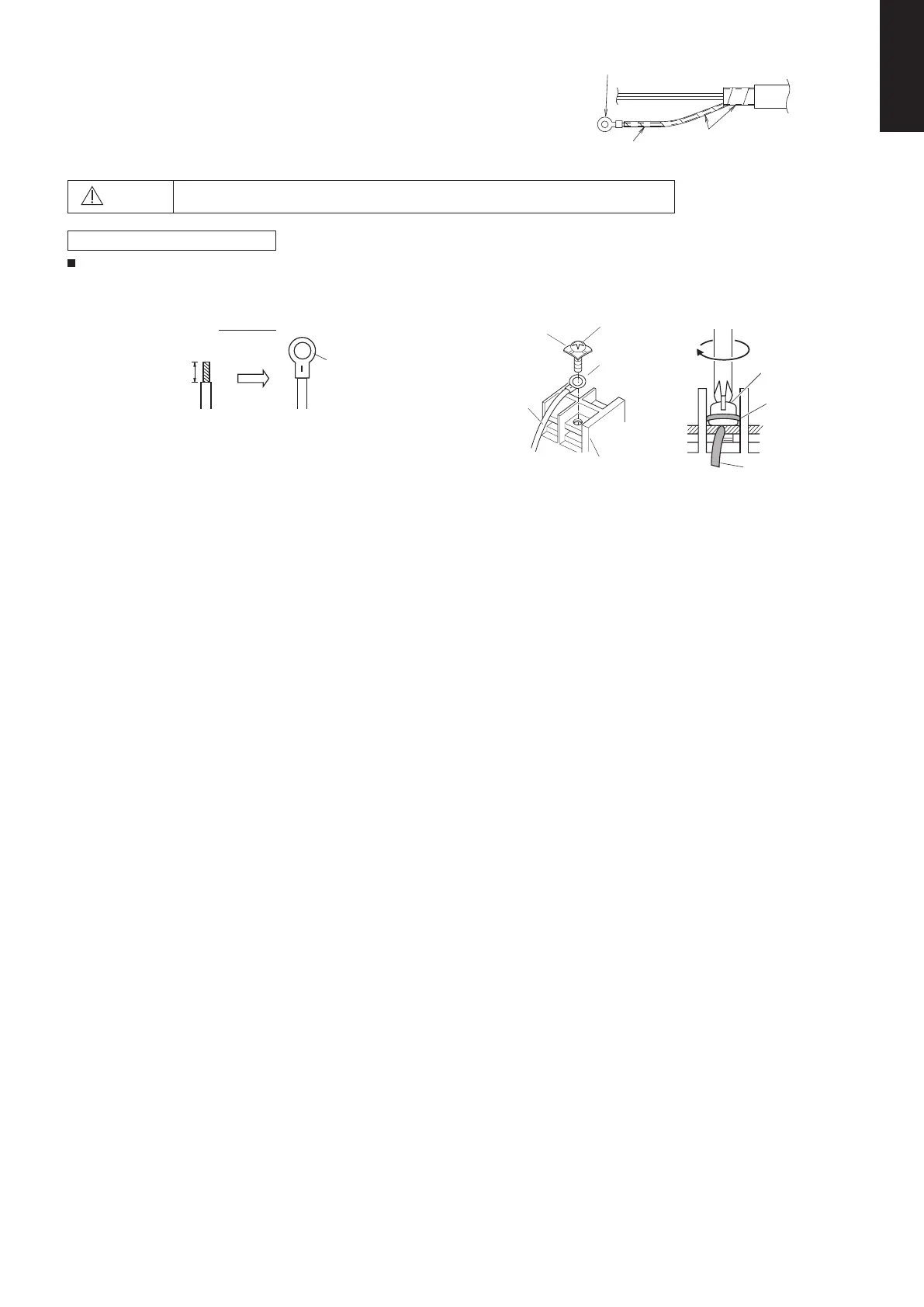
(Functional earthing) (Functional earthing)
Shielded wire
For the shield part of the shielded cable, twist the end out, crimp it with a round terminal, and connect it to
the functional earthing screw.
After crimping it with a round terminal, wrap it with insulating tape so there are no spaces and adjust it so
the shield part does not touch any live parts.
CAUTION
Be sure that the shield part of the shielded cable does not touch the terminal block or any live parts.
Failure to do so may lead to electric shock or fire.
How to connect wiring to the terminal
For stranded wires
(1) Cut the wire end with cutting pliers, then strip the insulation to expose
the stranded wire about 10 mm and tightly twist the wire ends.
Stranded wire
Strip 10 mm
Ring pressure
terminal
(2) Using a Phillips head screwdriver, remove the terminal screw(s) on the
terminal board.
(3) Using a ring connector fastener or pliers, securely clamp each stripped
wire end with a ring pressure terminal.
(4) Put the removed terminal screw through the ring pressure terminal and then
replace and tighten the terminal screw using a screwdriver.
Special washer
Screw
Terminal board
Ring pressure
terminal
Wire
Ring
pressure
terminal
Wire
Screw and Special
washer
Crimp the round terminal
Shield part
Wrap it well with insulating tape so
there are no spaces.
SM830281-00_欧州向け R32シングル TD&SM.indb 3 20/01/09 14:59:34