High-Speed Counter and Pulse Output
FPΣ User's Manual
138
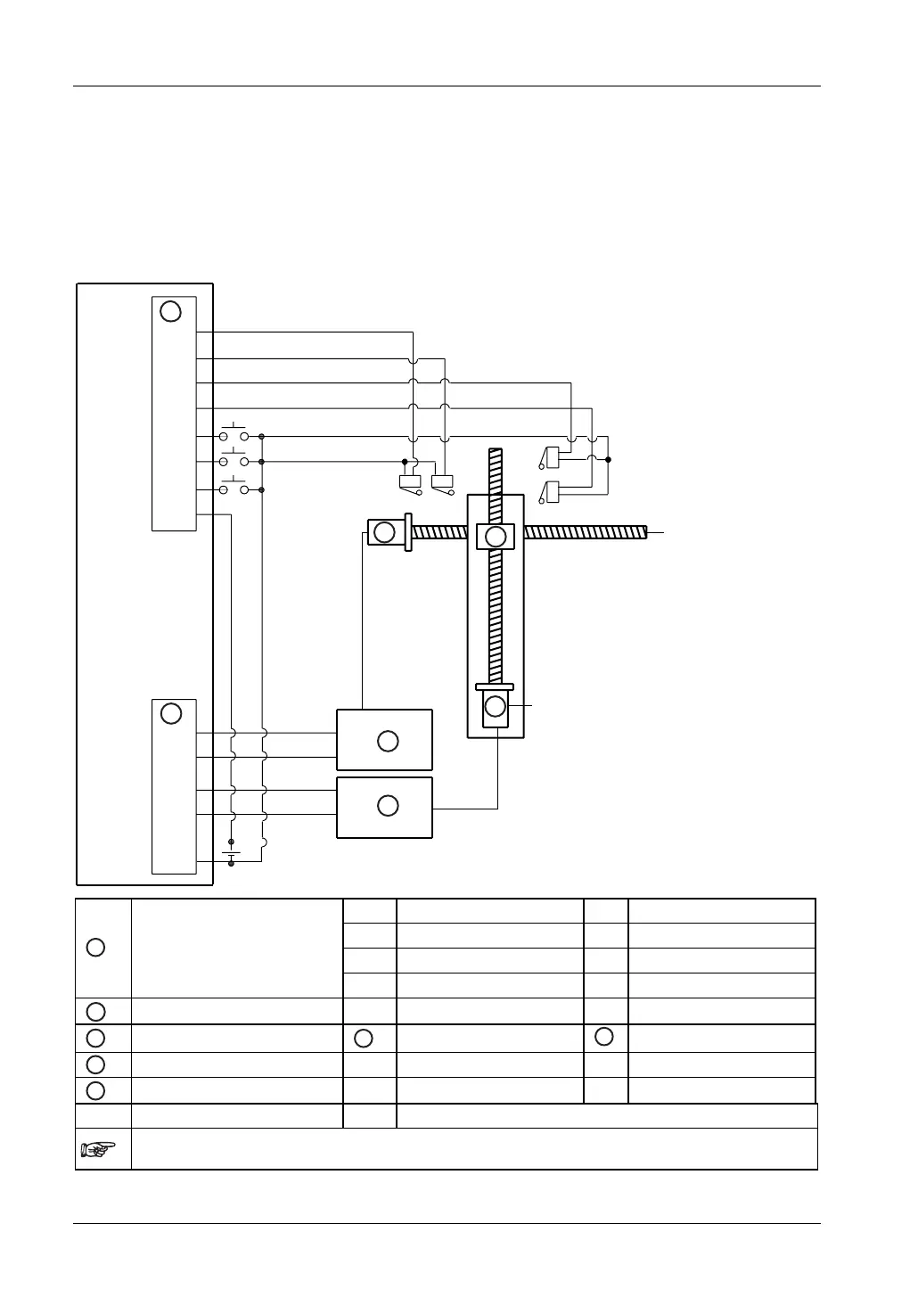
Wiring diagram for examples 4, 6, 7
The wiring diagram below applies to the following examples:
Example 4: home return in a backward direction (-) with 2 axes (see page
145)
Example 6: linear and circular interpolation control (see page
148)
Example 7: circular interpolation, continue mode (see page
149)
X2
X5
X3
XA
X0
XB
XC
CO M
Y0
Y3
+
Y1
Y4
-
D
CH0
CH2
B
C
24V DC
A
E
C
D
(+)
(-) (+)
(-)
X2
Home sensor
XA
Home return start
X0
Near home sensor
XB
Positioning start
X5
Home sensor
XC
Emergency stop
A
PLC: Input terminal
X3
Near home sensor
B
PLC: Output terminal Y0 CW pulse output
Y1
CCW pulse output
C
Motor driver
1
CW input
2
CCW input
D
Stepping motor
F
Moving table (+) + side
(-)
- side
CH0
Channel 0
CH2
Channel 2
If necessary, connect a resistor between PLC outputs and motor driver inputs. Please refer to the
manufacturer's documentation for correct wiring of the motor driver.
 Loading...


