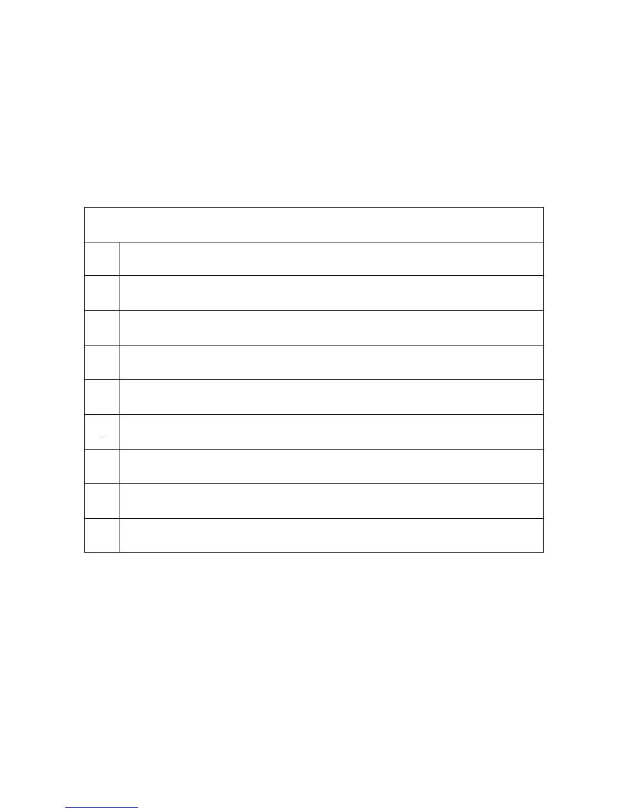
When an abnormality has occurred, the unit protection circuit operates and the TV is
reset to the stand-by mode. When that occurs, the defective block can be identified by
the number of blinks of the POWER LED on the front of the unit.
The following table identifies the areas where a problem is suspected according to the
number of times that the POWER LED blinks.
Power LED blinking timing chart for the TH-42PD25U-P
Number of Times the Power LED Blinks
2 Scan Driver 1 SOS2 (TPSOS2 (L6604) on SC Board)
3 3.3V SOS
4 5V SOS
5 Power Supply SOS (Pin 7 of connector P27)
6 -
7 SOS1 (Scan Driver 2) TPSOS1 (L6603) on SC Board)
8 -
9 SUS Driver (TPSOS3 on “SS” Board)
12 PA board
Table 5
46