When an abnormality has occurred, the unit protection circuit operates and the
TV is reset to the stand-by mode. At this time, the defective block can be
identified by the number of blinks of the POWER LED on the front of the unit.
The following table identifies the areas where a problem is suspected according
to the number of times that the POWER LED blinks.
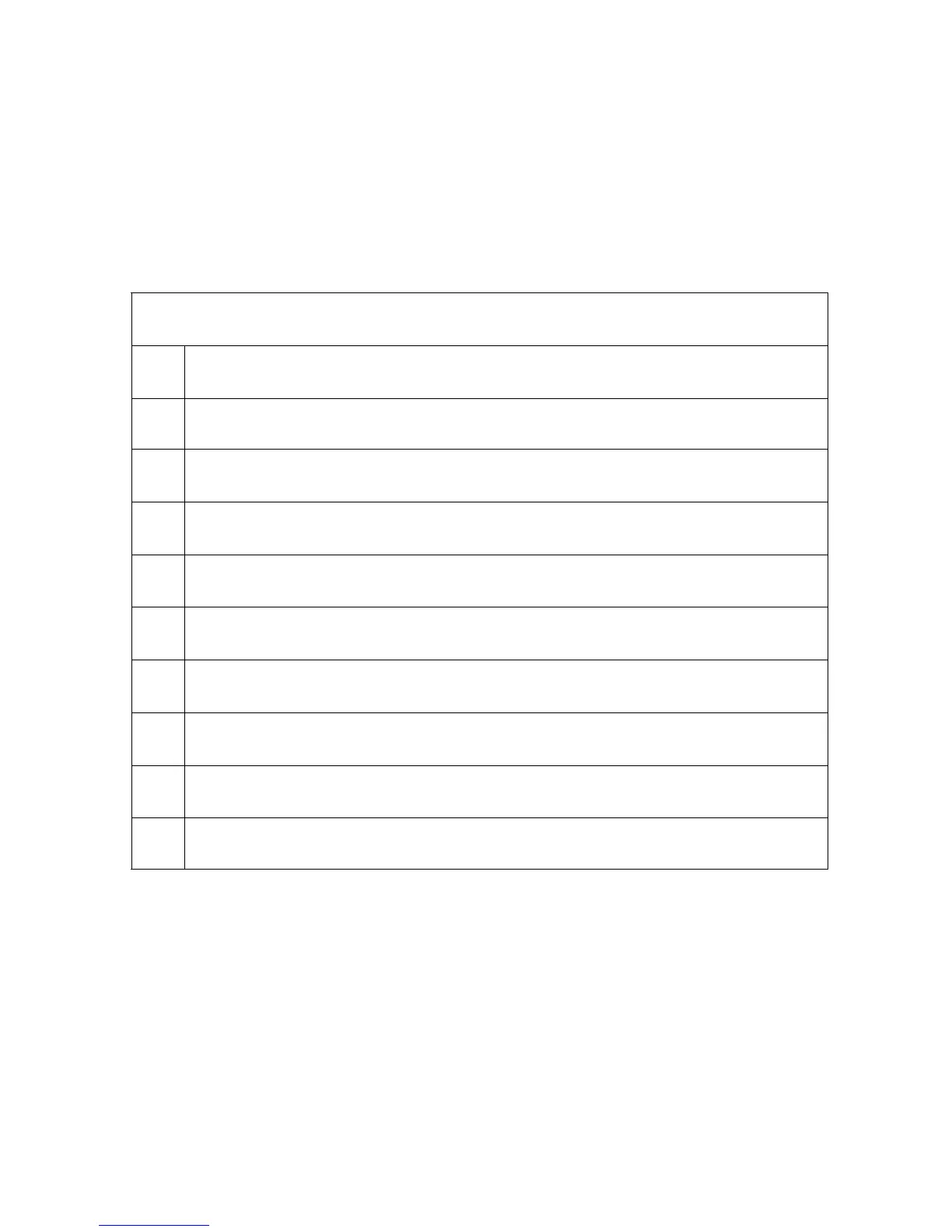
Power LED blinking timing chart for the TH-42XVS30
Number of Times the Power LED Blinks
1 -
2 SOS2 (TPSOS2 (L6604) on SC Board)
3 3.3V SOS
4 5V SOS
5 Power Supply SOS (Pin 7 of connector P27)
6 Fan SOS -
7 SOS1 (Scan Driver 2) TPSOS1 (L6603) on SC Board)
8 -
9 SUS Driver (TPSOS3 on “SS” Board)
12 Tuner Power
Table 9
86