|54 |
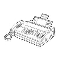
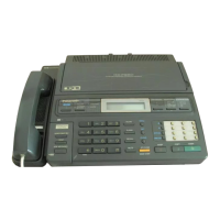
KX-F680BX/KX-F2681BX
3-7. DIGITAL BOARD SECTION
How to fix the digital board that don't start up the unit.
(1) OVER VIEW
If you see a human being down on the street, what will you do?
You may talk to him. But if he doesn't answer, you check his breath or pulse, don't you.
Why do we check them? Breath or pulse, we needs must do it to live. We start to check from most basic things to live.
Checking (or repair) the Board doesn't work is similar to it.
We should start to check from most basic things to work.
What is most basic to work?
1. POWER SUPPLY (+5V, +24V)
2. SOLDERING of ICs
3. OSCILLATOR (CLK) (SYSTEM CLK: 24MHz, MODEM CLK: 49.92MHz)
4. RESET
5. SIGNALS
ADDRESS BUS (A0~A15)
DATA BUS (D0~D7)
READ, WRITE (RD, WR)
CS (Chip select) (ROMCS, MDMCS)
"Board doesn't work" means that board has any problems in these most basic things.
This document is going to explaining the order of repair with flow chart at first and then explaining individual point of
those items in detail.
--- MEMO ---
MDM: modem (modulator/demodulator)
CLK: clock
ROM: read only memory
RAM: random access memory (SRAM: static RAM. DRAM: dynamic RAM)
RTC: real time clock
adr: address
RD: read
WR: write
 Loading...
