-12-
(Model KX-FT21BX/KX-FT21BX-W)
KX-FT21BX/KX-FT21BX-W
L
Error amp rectifier
Control IC
n
1
: n
2
Coil width value
of the ratio SecondaryPrimary
Load
24V
E
1
Gate signal
T
ON
T
OFF
T=1/f= fixing
T
ON
+ T
OFF
=T
Q
1
I
IN
D
1
E
2
V
0
V
R
light load
heavy load
0
0 1.0
= Duty ratio
=
Ton
T
0.5
1
2
3
4
V
0
/E
1
Output/Input voltage value of ratio
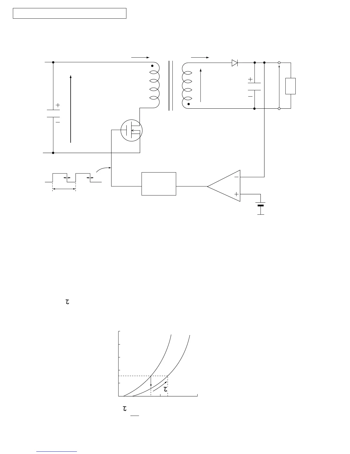
The following is an overview of how the power supply unit is controlled.
The control method of this power supply unit is pulse width modulation.
When Q
1
is ON, the energy is charged in the transfer primary coil according to E
1
.
When Q
1
is OFF, the energy is output from the secondary transfer as follows.
L ? D1 ? Load ? L
Then the power is supplied to the Load. When Q
1
is ON, power is not output from the secondary side.
The output voltage is fed back in the control IC according to the error amp rectifier.
Then depending on how T
ON
is controlled, stabilization occurs.
Also, when the current load becomes too large, in order to decrease the voltage output, the increase
in is controlled and the output voltage is stabilized.
Therefore, basically the timing: Ton/Toff of Q1 controls the output voltage.
increases

 Loading...