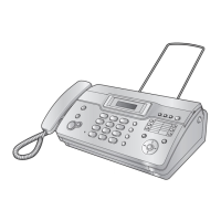
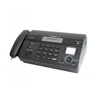
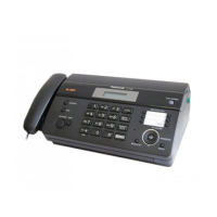
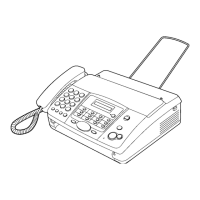
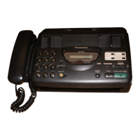
KX-FT21LA
- 126 -
MotorSwitch
Platen Roller Gear
Swing Gear B
Separation Roller Gear
Document Feed Roller Gear
G2
G1
G6
G5
G3
G7 (Drive
Motor Gear)
G8
Gear Arm
Spring
Swing Gear
A-2
Swing Gear
A-1
CAM (G4)
4-5. GEAR SECTION
This section shows how the motor-driven gear mechanism works in the main operations: FAX transmission, FAX reception the
motor and copying.
4-5-1. Mode Selection
When the motor attached to the Drive Motor Gear(G7) rotates counterclockwise (CCW), Swing Gear A-2 engages the CAM and
the
CAM turns counterclockwise to select a mode. There are three mode options controlled by the Switch : A: Transmit
mode, B: Receive mode and C: Copy mode. In Fig. B, you can see which mode is selected by the position of the rib in the CAM.
Fig.A [The operation is in the Transmit mode (A).]
Fig.B
A: Transmit mode B: Receive mode C: Copy mode
Switch
CAM (G4)
Rib