9
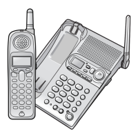
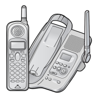
KX-TG2853BXS/KX-TG2854BXS/KX-TGA280BXS
4.2.3. Telephone Line Interface
<Function>
• Bell signal detection
• Clip signal detection
• ON/OFF hook circuit
• Audio circuits
• DTMF tone signal circuits
Bell signal detection:
In the standby mode, Q104 is open to cut the DC loop current and decrease the ring load.
When ring voltage appears at the TP L1T (A) and TP L1R (B) leads (When the telephone rings), the AC ring voltage is trans-
ferred as follows;
•A → R144 → C144 → Q146 → IC1 Pin 98 (RINGING)
•B → R145 → C145 → Q146 → IC1 Pin 98 (RINGING)
Clip (: Calling Line Identification Presentation: Caller ID) signal detection:
The Clip signal voltage is transferred as follows;
•A → C121 → R123 → R128 → IC1 Pin 112 (CIDinn)
•B → C131 → R133 → R138 → IC1 Pin 107 (CIDinn)
ON/OFF hook circuit:
In the standby mode, Q104 is open, and connected as to cut the DC loop current and to cut the voice signal. The unit is conse-
quently in an on-hook condition.
When IC1 detects a ring signal or press the TALK Key onto the handset, Q105 turns on and Q104 turns on, thus providing an
off-hook condition (active DC current flow through the circuit) and the following signal flow is for the loop current.
•A → D103 → Q104 → Q171 → R178 → R179 → D103 → B [OFF HOOK]
4.2.4. Transmitter/Receiver
Base Unit and Handset mainly consist of RF Module and BBIC.
Base Unit and Handset transmit/receive voice signal and data signal through the antenna on carrier frequency.
 Loading...