12
KX-TG8421E/KX-TG8422E/KX-TG8423E/KX-TG8424E/KX-TGA840E
4.4. Circuit Operation (Handset)
4.4.1. Outline
Handset consists of the following ICs as shown in Block Diagram (Handset) (P.11).
• DECT BBIC (Base Band IC): IC1
- All data signals (forming/analyzing ACK or CMD signal)
- All interfaces (ex: Key, Detector Circuit, Charge, DC/DC Converter, EEPROM, LCD, RF Power Amp.)
- PLL Oscillator
- Detector
- Compress/Expander
- Reception
• RF Power Amp: IC801
- Amplifier for transmission
• EEPROM: IC3
- Temporary operating parameters (for RF, etc.)
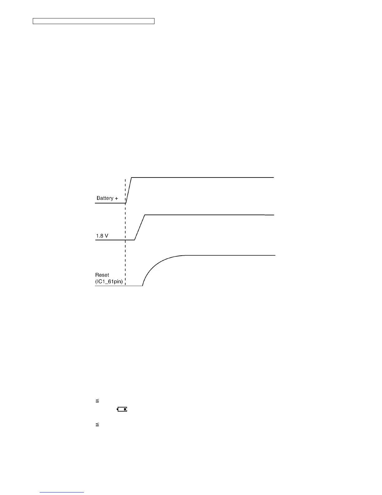
4.4.2. Power Supply Circuit/Reset Circuit
Circuit Operation:
When power on the Handset, the voltage is as follows;
BATTERY(2.2 V ~ 2.6 V: BATT+) → F1 → Q2 (1.8 V), IC1-43pin (2.5V)
The Reset signal generates IC1 (61 pin) and 1.8 V.
4.4.3. Charge Circuit
Circuit Operation:
When charging the handset on the Base Unit, the charge current is as follows;
DC+(6.5 V) → D1 → R56 → R55 → D22 → CHARGE+(Base) → CHARGE+(Handset) → Q4 → D7→ F1 → BATTERY+... Bat-
tery...
BATTERY- → R45 → GND → CHARGE-(Handset)→ CHARGE-(Base) → GND → DC-(GND)
In this way, the BBIC on Handset detects the fact that the battery is charged.
The charge current is controlled by switching Q9 of Handset.
Refer to Fig.101 in Power Supply Circuit (P.9).
4.4.4. Battery Low/Power Down Detector
Circuit Operation:
“Battery Low” and “Power Down” are detected by BBIC which check the voltage from battery.
The detected voltage is as follows;
• Battery Low
Battery voltage: V(Batt) 2.25 V ± 50 mV
The BBIC detects this level and " " starts flashing.
• Power Down
Battery voltage: V(Batt) 2.0 V ± 50 mV
The BBIC detects this level and power down.
4.4.5. Speakerphone
The hands-free loudspeaker at SP+ and SP- is used to generate the ring alarm.

 Loading...