EasyManua.ls Logo

Panasonic Lumix DMC-TZ1EB User Manual

Panasonic Lumix DMC-TZ1EB
63 pages
To Next Page IconTo Next Page
Page #1 background imageLoading...
Page #1 background image
© 2006 Matsushita Electric Industrial Co., Ltd. All
rights reserved. Unauthorized copying and distribu-
tion is a violation of law.
ORDER NO. DSC0603011CE
B26
Digital Camera
DMC-TZ1PP
DMC-TZ1PL
DMC-TZ1EB
DMC-TZ1EE
DMC-TZ1EF
DMC-TZ1EG
DMC-TZ1EGM
DMC-TZ1GC
DMC-TZ1GK
DMC-TZ1GN
DMC-TZ1GT
DMC-TZ1SG
Vol. 1
Colour
(S)...........Silver Type
(K)...........Black Type
(A)...........Blue Type (except PL/GN/GT)

Table of Contents

Question and Answer IconNeed help?

Do you have a question about the Panasonic Lumix DMC-TZ1EB and is the answer not in the manual?

Panasonic Lumix DMC-TZ1EB Specifications

General IconGeneral
BrandPanasonic
ModelLumix DMC-TZ1EB
CategoryDigital Camera
LanguageEnglish

Summary

Service Manual Introduction and Warnings

WARNING

Important safety warning regarding service by experienced technicians only.

Safety Precautions

General Safety Guidelines

General safety guidelines for servicing electronic equipment and preventing hazards.

Leakage Current Checks

Procedures for performing cold and hot checks of leakage current.

Capacitor Discharge Procedure

Battery and AC Safety

Electrostatic Discharge (ESD) Prevention

Techniques to reduce component damage from electrostatic discharge (ESD) to sensitive devices.

AC Mains Lead and Fuse Replacement

Safety precautions for handling the AC mains lead, including fuse replacement.

Lithium Battery Replacement

Replacement Procedure

Step-by-step procedure for replacing the lithium battery in the camera.

Service Navigation

Model Suffix Identification

Methods to identify camera model suffixes based on nameplate and safety registration marks.

Initial Settings Procedure

Specifications

Component Locations

External Controls and Components

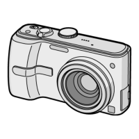
Identification of external controls and components on the camera body.

Service Mode

Error Code Memory Function

Details on the error code memory function, including display, reading, and returning to normal display.

Firmware Version Confirmation

Service Fixtures and Tools

Required Tools and Fixtures

List and images of specialized fixtures and tools required for servicing the unit.

Disassembly and Assembly

Disassembly Flow Chart

Flowchart illustrating the sequence for disassembling the camera unit.

PCB Locations

Diagram showing the physical location of main PCBs within the camera.

Disassembly Procedures

Rear Case Unit Removal

Procedure for removing the rear case unit, including screw types and connector handling.

LCD Unit Removal

Main PCB Removal

Power/Top PCB Removal

Lens Unit Removal

CCD Unit Removal

Measurements and Adjustments

Replaced Part Adjustment Matrix

Table showing necessary adjustments based on replaced parts like main PCB, lens, or CCD.

Maintenance

Lens and LCD Panel Cleaning

Instructions for cleaning the camera lens and LCD panel using appropriate tools.

Schematic Diagrams

Interconnection Diagram

Diagram showing interconnections between major PCBs and components.

Power Schematic Diagram

Lens Drive Block Diagram

Replacement Parts List

Parts List Details

Detailed list of replacement parts, including part numbers and descriptions, organized by component type.

Exploded Views

Frame and Casing Section

Exploded view of the camera's frame and casing components.

Related product manuals