21
8.3. Disassembly Procedure
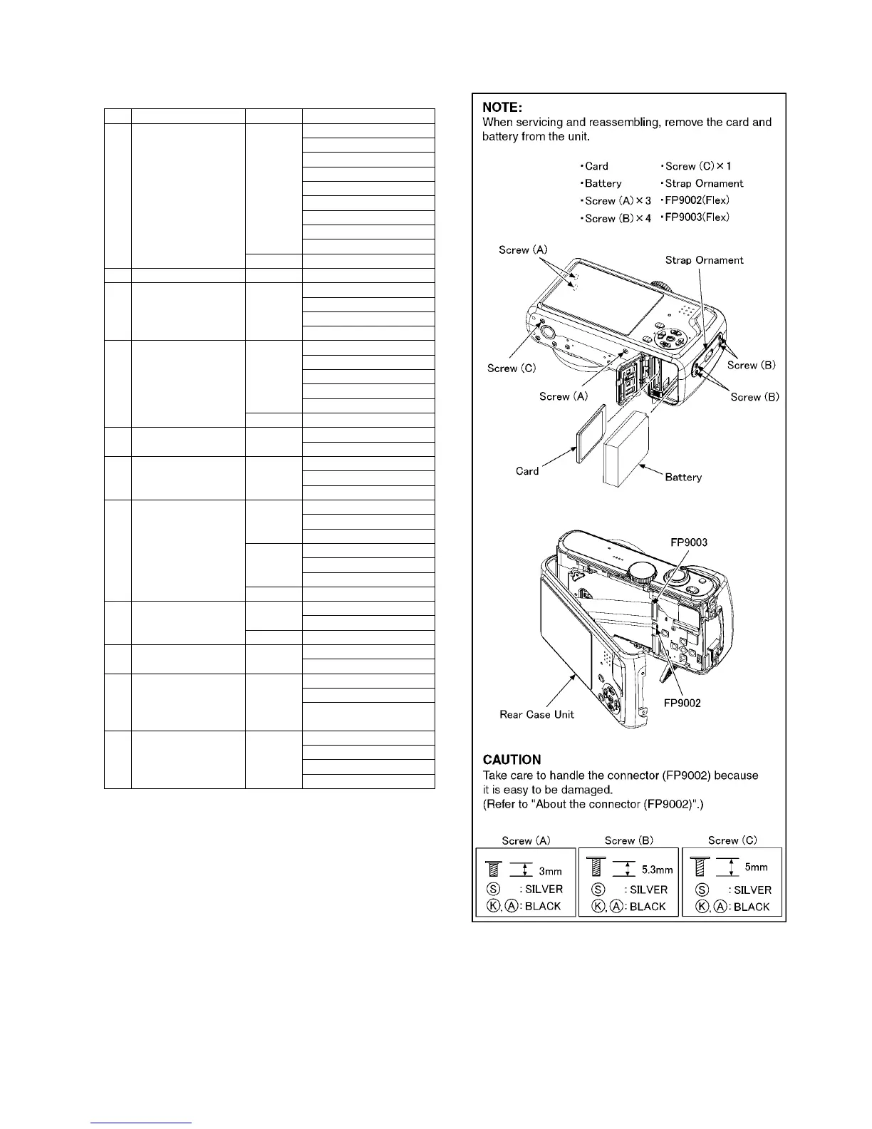
8.3.1. Removal of the Rear Case Unit
Fig. D1
No. Item Fig Removal
1 Rear Case Unit Fig. D1 Card
Battery
3 Screws (A)
4 Screws (B)
1 Screw (C)
Strap Ornament
FP9002(Flex)
FP9003(Flex)
Rear Case Unit
Fig. D2 About the connector
2 LCD Unit Fig. D3 LCD Unit
3 Front Case Unit Fig. D4 3 Screws (D)
2 Screws (E)
1 Screw (F)
Front Case Unit
4 Main P.C.B. Fig. D5 1 Screw (G)
FP9001(Flex)
FP9004(Flex)
PS9001(Connector)
Main P.C.B.
Fig. D6 About the connector
5 Top Operation Unit Fig. D7 1 Locking tab
Top Operation Unit
6 Jack P.C.B. Fig. D8 PP2001(Connector)
1 Screw (H)
Jack P.C.B.
7 Power/Top P.C.B. Fig. D9 2 Screws (I)
1 Locking tab
Top Ornament Unit
Fig. D10 5 Locking tabs
Top Cover Unit
Power/Top P.C.B.
Fig. D11 NOTE: (When installing)
8 Lens Unit Fig. D12 FP9501(Flex)
Lens Unit
Fig. D13 About the connector
9 SD/AFE P.C.B. Fig. D14 1 Screw (J)
SD/AFE P.C.B.
10 Battery Door Unit
Battery Case Unit
Fig. D15 Battery Door Shaft
Battery Door Spring
Battery Door Unit
Battery Case Unit
11 Battery Case Fig. D16 2 Locking tabs
Battery Case Upper
Battery Terminal Spring
Battery Case

 Loading...