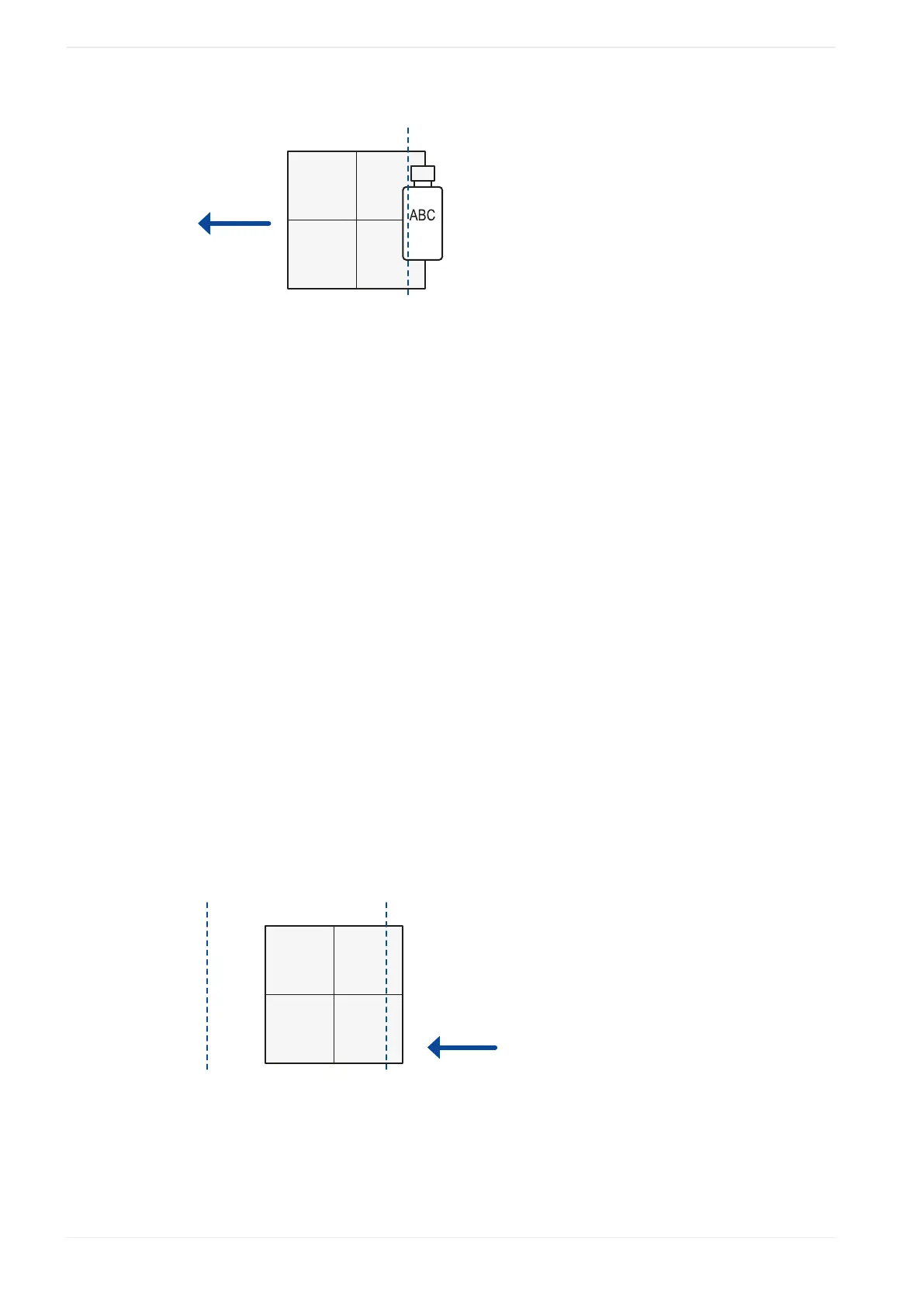
23 On-the-fly marking
(1)
(2)
(3)
(4)
(1)
Moving direction
(2)
Lasing start boundary
(3)
Workpiece
(4)
Marking field
Remarks
• If there is no on-the-fly marking error, the recommended position of the lasing start
boundary is the center of the marking field (default setting).
• If an error occurs because the marking speed cannot follow the line speed, specify an
upstream position (positive value) for the lasing start boundary.
• It is not necessary to conform the lasing start boundary to the position of the marking data
in the marking field.
• Place the lasing start boundary downstream of the trigger detecting position.
“Overrun correction”
If the characters at the marking start position are distorted, set a larger value for this
parameter. A larger value results in a longer marking time.
Example
With on-the-fly marking it is possible to mark data that is placed outside of the marking field.
The following drawing shows an example.
ABCDEFGHIJKLMNOPQRSTU...
(1)(1)
(2)
(3)
(4)
(1)
Workpiece reference boundary
(2)
Lasing start boundary
(3)
Moving direction
(4)
Marking field
246 ME-NAVIS2-OP-1