24 System settings
3. You can specify different parameters to correct the marking position.
The following figure shows these parameters.
+Y
-Z
+X
-X
+Z
+
-
-Y
(1)
(2)
(3)
(5)
(4)
(1)
X-axis offset
(2)
Y-axis offset
(3)
Z-axis offset
(4)
Rotation offset (-)
(5)
Rotation offset (+)
• “X-axis offset [mm]”, “Y-axis offset [mm]”:
Enter a value to position the marking field along the x-axis and y-axis.
With the x-/y-axis offset, you can shift the position of the marking field coordinates.
However, you cannot use the whole original marking field, because the available
range is defined by the lens and other optical devices.
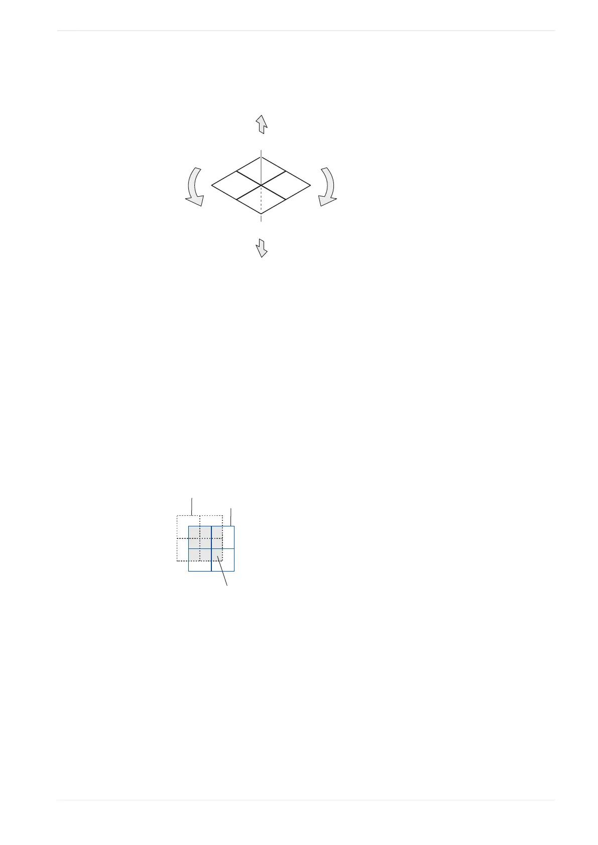
Example
The following drawing is an example to illustrate the available marking field (gray)
with x-/y-axis offset. The available marking field is restricted to the area that overlaps
the original position of the marking field.
(1)
(2)
(3)
(1)
Original position of the marking field
(2)
Offset x-/y-position of the marking field
(3)
Available area for marking
• “Z-axis offset [mm]” (LP-GS except LP-GS051-L):
Enter a value to position the marking field along the z-axis.
• “Rotation offset [°]”:
Specify an angle to rotate the marking field. The rotation center is the center of the
marking field.
• “X-scaling [%]”, “Y-scaling [%]”:
Enlarge or reduce the size of the marking field by a specific percentage. The scaling
center is the center of the marking field.
ME-NAVIS2-OP-1 263