14 –
ENGLISH
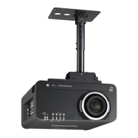
Location and function of each part (continued)
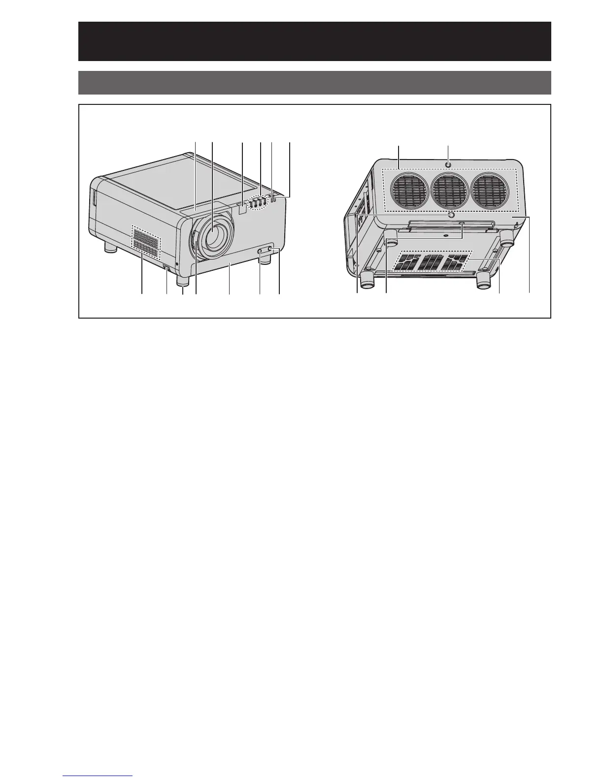
Front
Projector Main Unit
Rear
1
Projection lens cover ・・・・・・・・・・・・・・・・・・ (p. 34)
2
Projection lens (optional)
Lens for projecting images on the screen.
3
Remote control receiver window (front)
・・・・・・・・・・・・・・・・・・・・・・・・・・・・・・・・・・・・・・ (p. 17)
This window receives the signal beam emitted
from the remote control.
4
LAMP (LAMP1, LAMP2, LAMP3, LAMP4)
monitor ・・・・・・・・・・・・・・・・・・・・・・・・・・・・・ (p. 109)
These LEDS indicate the status of each lamp -
GREEN for “In Use”, RED for “End-of-Life”, and
BLINKING RED for “Error Condition”.
5
Temperature monitor (TEMP) ・・・・・・・・・ (p. 109)
These LEDs illuminate and flash to indicate lamp
warmup intervals, abnormal internal temperatures,
or cooling fan errors.
6
Power indicator lamp ・・・・・・・・・・・・・・・・・ (p. 35)
The lamp lights in red when the MAIN POWER
switch is turned to “ l ”. It turns to green when the
POWER ON button of the remote control or the
main unit is pressed.
7
Air intake vents
During installation, ensure adequate airflow to
these vents.
8
Burglar hook
Attach a commercial burglar prevention cable to
this hook port.
9
Adjustable feet ・・・・・・・・・・・・・・・・・・・・・・・ (p. 20)
Use these feet to adjust the tilt of the projector.
(Adjustable feet are provided at the front and rear,
right and left.)
j
Projection lens cover lock button ・・・・・・ (p. 34)
Press these side buttons to unlock the lens
cowling, pulling it forward to remove. Centering
the lens first may ease removal.
k
Air filter ・・・・・・・・・・・・・・・・・・・・・・・・・・・・・ (p. 110)
l
Air filter cleaning monitor・・・・・・・・・(pp. 79, 110)
This blinks blue while the air filter is being cleaned.
It lights red when there is a problem with the air
filter.
m
Filter cleaning unit fixing screw ・・・・・・・ (p. 110)
This is used to secure the air filter cover.
n
Air exhaust vents
Hot air comes out of the air exhaust vents.
o
Lamp unit cover screw ・・・・・・・・・・・・・・・ (p. 113)
This is used to secure the lamp unit cover.
p
Remote control receiver window (rear) ・ (p. 17)
This also receives the signal beam coming from
the remote control.
q
Remote control receiver window (bottom)
・・・・・・・・・・・・・・・・・・・・・・・・・・・・・・・・・・・・・・ (p. 17)
This also receives the signal beam coming from
the remote control.
r
Air intake vents
During installation, ensure adequate airflow to
these vents.
s
Lamp unit cover ・・・・・・・・・・・・・・・・・・・・・ (p. 113)
This hinged panel swings down for lamp
replacement.
12 3456
7
n
89j k l m
o
pq r s