Do you have a question about the Panasonic PT-VX400U and is the answer not in the manual?
Essential safety parts and FCC compliance information for preventing hazards.
Guidelines for servicing using lead-free solder for environmental protection.
Warning to use UV radiation eye and skin protection during servicing.
General guidelines for safe projector maintenance and servicing.
Procedure to measure leakage current for preventing electric shock.
Safety measures for UV radiation and UHM lamps during operation and servicing.
Details on power supply, consumption, LCD panel, lens, lamp, and light output specifications.
Supported scanning frequencies for RGB, YPBPR, Video, and HDMI signals.
Details on all projector connection terminals like HDMI, Audio, LAN, and control ports.
Information on dimensions, weight, operating temperature, and humidity.
Details on the thermal fuse (SW902) and lamp cover switch (SW901) for safety.
Information on the main fuse (F601), its type, and replacement procedure.
Projector shutdown behavior due to high temperature or fan failure, indicated by LED status.
Instructions for cleaning the projector's outer case and the front glass surface of the lens.
Procedure for cleaning or replacing air filters to maintain cooling efficiency and prevent overheating.
Steps to reset the filter usage counter after replacing air filters.
Instructions for attaching the filter cover when mounting the projector on a ceiling.
Details on the lamp unit, precautions, and recommended replacement procedure.
On-screen icons and indicator lights signaling the need for lamp replacement.
Detailed steps for safely removing the old lamp unit and installing a new one.
Details on the warning message for non-standard lamps and potential function limitations.
Methods for cleaning optical parts, including air spray and disassembly procedures.
Instructions for cleaning the projection lens and the projector cabinet.
Description of security functions: Key lock, PIN code lock, and Logo PIN code lock.
Steps to reset security functions like Key lock, PIN code lock, and Logo PIN code lock.
Table detailing function restrictions in Eco and Network standby modes.
Procedure for removing the cabinet top, lamp cover, and cabinet front assembly.
Steps to remove the main board, AV board, and cooling fans (FN904, FN905).
Procedure for removing the speaker, lamp assembly (LP900), and optical unit.
Steps to remove the fan (FN906), thermal fuse (SW902), and power board.
Procedure for removing the mounting duct and cooling fans (FN901, FN902, FN903).
Instructions for reforming and routing cables during disassembly and reassembly.
Procedure for removing the LCD panel/prism assembly, with notes on handling sensitive parts.
Important notice regarding LCD panel replacement, advising against separate disassembly.
Procedure for removing the polarized glass assembly, including notes on handling and mounting.
Procedure for removing the projection lens from the optical unit.
Procedure for disassembling the integrator and condenser lenses (OUT).
Procedure for removing the top part of the optical unit.
Procedure for removing the relay lens assembly.
Diagrams showing the correct locations and directions for mounting optical parts in the optical unit.
Actions required after main board replacement, including data transfer and setting adjustments.
Optical adjustments required after parts replacement, including contrast and center adjustments.
Electrical adjustments like auto calibration, white balance, and keystone correction.
Procedure for adjusting projector contrast by manipulating the G-polarized glass mounting base.
Procedure for optical center adjustment, focusing on condenser lens positioning.
Procedure for adjusting the relay lens to correct color shading on the screen.
Procedure for condenser lens adjustment to eliminate color shading on the screen.
Guide on how to enter and navigate the service adjustment menu for modifying settings.
Information on factory fine-tuned circuits and cautions against unauthorized adjustments.
Procedures for fan voltage, PC auto calibration, gain, and pedestal adjustments.
Procedures for auto calibration and fine-tuning for component and video inputs.
Procedures for gamma, white balance, and color shading adjustments using service software.
Procedure for adjusting keystone offset using service mode and SELECT button.
Diagram showing the locations of test points on the main board for electrical adjustments.
Table of service adjustment items, initial values, ranges, and notes for readjustment.
Service data for AD Converter (PW190) and Sync Processor functions.
Adjustment data for Video Decoder, General settings, and Deinterlacer.
Various deinterlacer modes and noise reduction settings for different signal types.
Settings for 2:2 and 2:3 pull-down modes, affecting motion and film processing.
Settings for center contrast, brightness, color, tint, and sharpness for optimal picture display.
Extensive list of electrical adjustment parameters covering various functions and settings.
Settings for logo prohibition, RS232C baudrate, and PJLink enable.
Settings related to lamp PWM, filter warning display, and factory default execution.
Configuration for frame lock option, affecting PC signal and input signal frequency.
Adjustment parameters for controlling lamp brightness levels and cooling gain.
Settings for VBI slice level, affecting projector registers.
Settings for fan voltage adjustment and operational options like Hi-Land switch.
Memorized temperature error settings and control range settings for fans.
Settings for fan start voltage, cooling speed, lamp voltage dimmer, and fan dimmer.
Procedures for common auto calibration and RGB auto calibration.
Auto calibration procedures for CVBS/S-Video and YCbCr inputs.
Custom aspect ratio settings and AutoPC adjustment parameters.
Procedures for setting the projector model number via service menu groups.
Adjustment parameters for Composite (NTSC, PAL, SECAM) and SCART signals.
Adjustment parameters for YCbCr signals (480i, 575i), covering dots and porch settings.
Detailed adjustment parameters for various YCbCr signals including 575i, 480P, 575P, 720P, and 1080i.
Detailed adjustment parameters for various RGB Video signals including 480i, 575i, 480P, 575P, 720P, and 1080i.
Adjustment parameters for color shading offset for R, G, B components.
Overall block diagram showing the main components and their interconnections within the projector chassis.
Block diagram illustrating the system control architecture, including CPU, power, and fan circuits.
Block diagram showing the lamp control circuit, including ballast, power, and thermal fuse.
Block diagram illustrating the audio circuit, including HDMI audio decoder, amplifier, and speaker connections.
Block diagram of the power supply and protection circuits, including voltage regulation and thermal sensors.
Block diagram of the fan control circuit, showing fan connections and error detection.
Explanation of projector status indicated by Power, Lamp Replace, and Warning LEDs.
Steps to diagnose 'No power' issues by checking LEDs, power circuits, and lamp cover switch.
Troubleshooting steps for 'No picture' issues based on input sources and signal checks.
Troubleshooting steps for 'No sound' issues, checking audio signals and output circuits.
List of Scaler I/O port functions (PW190) with pin numbers, signal names, descriptions, and I/O types.
Block diagrams for FA5550NG (Power Control) and LC87F2G08AUSSOP (Sub CPU).
Block diagrams for SP3232ECYP (RS-232C Driver) and L3E06200P0A (LCD Driver).
Block diagrams for L3E07111 (Gamma Correction) and TLV320AIC3105 (Audio Control).
Internal block diagram of the PW190 Scaler IC (IC301), showing its functional modules.
Block diagram for the L3E08030F0A Dimmer Control IC (IC9001).
Block diagrams for MR4010 (Power OSC) and AX11005 (Network).
Block diagram for the TPS54286 DC-DC converter IC (IC7811).
Diagram showing the location of parts within the projector's cabinet top assembly.
Diagram showing the location of parts within the projector's cabinet bottom-1 assembly.
Diagram showing the location of parts within the projector's cabinet bottom-2 assembly.
Diagram showing the location of parts related to the projector's projection lens.
Diagram showing the location of parts for the integrator and condenser lens assemblies.
Diagrams showing the location of the polarized glass and LCD panel/prism assemblies.
Diagram showing the location of parts for the relay lens (OUT) assembly.
Diagram showing the location of various optical parts within the optical unit.
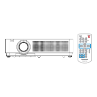
Diagrams of included accessories such as remote control, manual, CD-ROM, cables, and strap.
List of mechanical parts for the projector cabinets and chassis.
List of optical parts and screws used in the projector.
Details on capacitor types, tolerance symbols, rated voltage, and part number list.
Details on resistor types, performance symbols, rated wattage, and part number list.
List of assembled boards and transistors with part numbers and descriptions.
List of integrated circuits and components not on main boards like motors and speakers.
List of integrated circuits with part numbers and descriptions.
List of capacitors with part numbers, type, and voltage rating.
Continuation of the capacitor list with part numbers, type, and voltage rating.
Continuation of the capacitor list with part numbers, type, and voltage rating.
Continuation of the capacitor list with part numbers, type, and voltage rating.
Continuation of the capacitor list with part numbers, type, and voltage rating.
Continuation of the capacitor list with part numbers, type, and voltage rating.
Continuation of the capacitor list with part numbers, type, and voltage rating.
Continuation of the capacitor list with part numbers, type, and voltage rating.
List of resistors with part numbers, description, and wattage.
Continuation of the resistor list with part numbers, description, and wattage.
Continuation of the resistor list with part numbers, description, and wattage.
Continuation of the resistor list with part numbers, description, and wattage.
Continuation of the resistor list with part numbers, description, and wattage.
List of coils with part numbers and descriptions.
Continuation of the coil list with part numbers and descriptions.
List of diodes with part numbers and descriptions.
Continuation of the diode list with part numbers and descriptions.
Lists of capacitors and resistors with part numbers and descriptions.
List of assembled boards and transistors with part numbers and descriptions.
List of integrated circuits and components not on main boards like motors and speakers.
Continuation of lists for capacitors, resistors, and diodes with part numbers.
Lists of transformers, coils, and miscellaneous parts with part numbers.
List of assembled boards and capacitors with part numbers and descriptions.
List of resistors with part numbers and descriptions.
Main schematic diagram showing the projector's electrical system architecture and component interconnections.
Important safety cautions and notes specifically for interpreting and working with the schematic diagrams.
Schematic details for Scaler (IC301), HDMI Receiver (IC8001), and Audio circuits.
Schematic details for Sub CPU (IC9885), Flash Memory (IC801), and Scaler (IC301) ICs.
Schematic details for Power Control (IC9001), Gamma Correction (IC401), and Accelerator Sensor ICs.
Schematic details for the RC receiver, key switch, and LED indicators.
Schematic details for the lamp ballast, power supply, and ID connect circuits.
Schematic showing interconnections between Sub CPU, Power Control, and Scaler ICs.
Schematic details for Gamma Correction, Accelerator Sensor, and other related ICs.
Schematic diagrams illustrating the red, green, and blue signal paths and related ICs.
Layout diagrams for the RC board (Side A/B) and Power board (Side A/B).
Layout diagram for the main PCB (Side A), showing component placement.
Layout diagram for the AC filter PCB (Side A), showing component placement.
Layout diagram for the main PCB (Side B), showing component placement.
Layout diagram for the AC filter PCB (Side B), showing component placement.
Layout diagrams for the Sub Power and ID Connect boards (Side A/B).
Layout diagrams for the AV board (Side A/B), showing component placement.