•
• •
• SMPS Module P.C.B. Replacement:
1. This model uses SMPS Module P.C.B. to provide the necessary supply voltages for the unit.
2. It is advisable to replace the SMPS Module P.C.B. once upon detecting of non-working conditions. Do not attempt to
repair or replace it by components.
3. Non-working conditions include:
O
OO
OWith AC supply but no supply voltages after checking at CN2 and/or CN3 respectively.
O
OO
OBroken fuse. (Substitute compatible part for fuse: K5D312BNA005)
O
OO
OWire connection problem.
O
OO
ONon-working parts in SMPS Module P.C.B. (Check components)
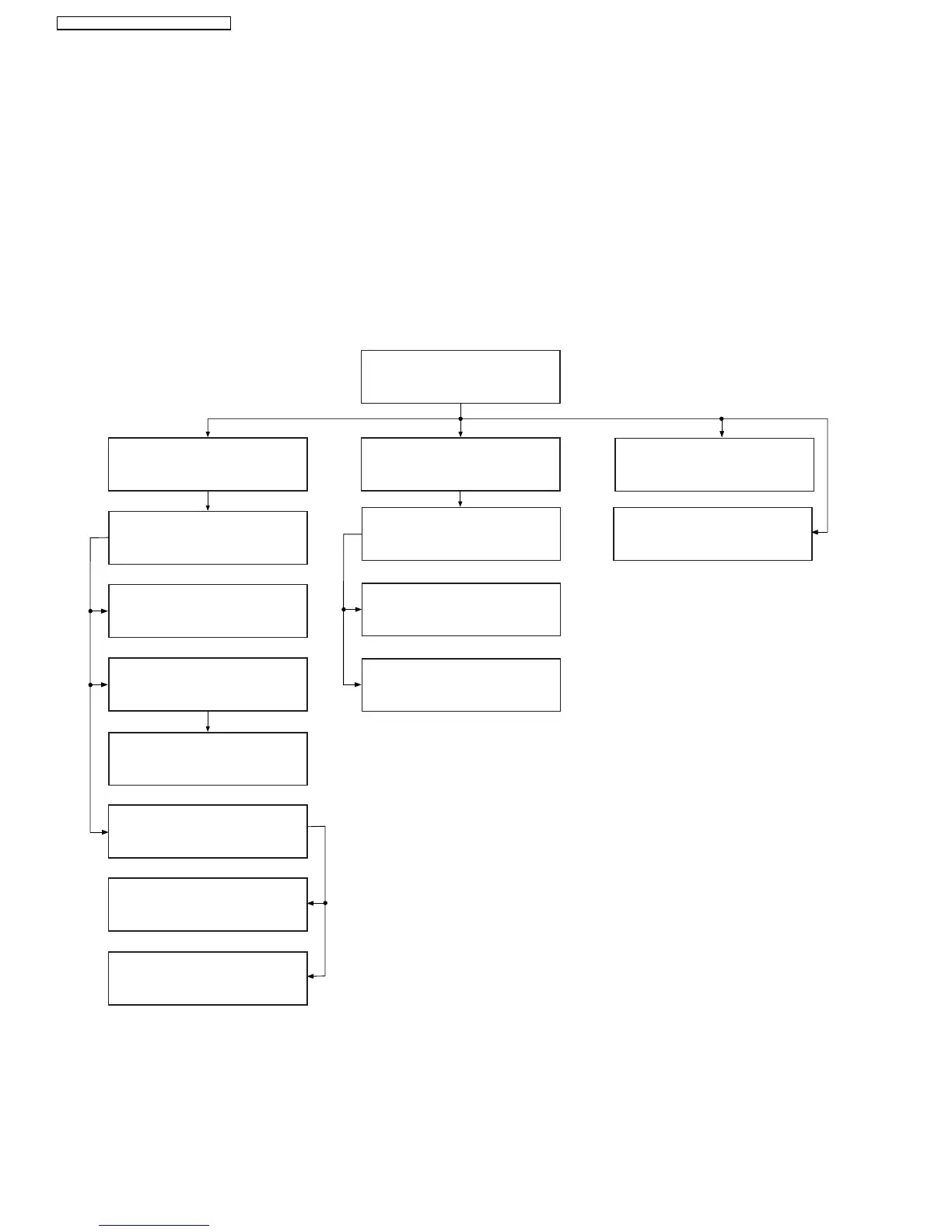
9.1. Disassembly Flow Chart
9.4. DVD Lid
9.9. Rear Panel
9.3. Top Cabinet
9.16. SMPS Module
P.C.B.
9.8. USB P.C.B.
9.7. Panel P.C.B.
9.6. Volume P.C.B.
9.5. Front Panel
9.11. DVD Module P.C.B.
9.15. Regulator IC
(IC2903)
9.13. Main P.C.B.
9.17. Tuner Extent
P.C.B.
9.12. USB Relay P.C.B.
9.10. DVD Mechanism
Unit
9.14. Digital Amp IC
(IC5100/IC5200/IC5300)
36
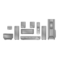
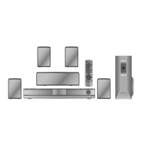
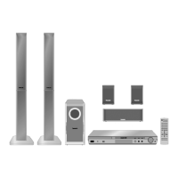
SA-PT160E / SA-PT160EB / SA-PT160EG