Step 2 Remove 2 screws at bottom chassis.
Step 3 Release the 2 claws, and then draw the front panel
ass’y forward.
·
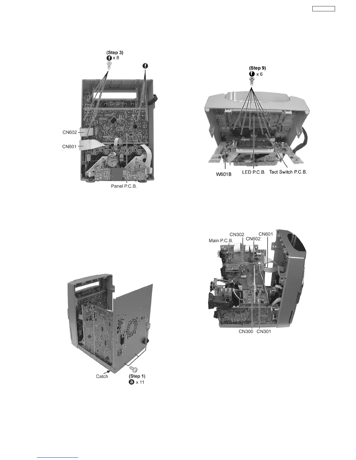
Disassembly of Panel P.C.B.
·
Follow the (Step 1) - (Step 2) of Item 17.2.
·
Follow the Disassembly for the Top Ornament Unit of Item
17.4.
Step 1 Remove the 11 screws.
Step 2 Push the catch outwards & draw the rear panel
backwards to remove it.
Step 3 Detach connectors CN601, CN602 and CN302.
Step 4 Lift up the Main P.C.B. to remove it.
Caution Note:
Avoid using/ exerted strong force when removing the Main
P.C.B.
Step 4 Remove the 8 screws.
Step 5 Disconnect FFC board (CN601 & CN602).
Step 6 Draw the Panel P.C.B. forward to remove it.
·
Disassembly of Tact Switch P.C.B. & LED P.C.B.
Step 7 Remove the volume knob.
Step 8 Disconnect connector W601B.
Step 9 Remove 6 screws.
Step 10 Draw Tact Switch P.C.B. forward.
·
Disassembly of Power P.C.B.
−
− −
− Follow the (Step 1) - (Step 2) of Item 17.2.
−
− −
− Follow the Disassembly for the Top Ornament Unit of
Item 17.4.
−
− −
− Follow the (Step 1) - (Step 4) of Item 17.5.
−
− −
− Follow the (Step 1) - (Step 4) of Item 17.6.
17.7. Disassembly of Main P.C.B., Power P.C.B., Transformer P.C.B. &
Voltage Selector P.C.B.
35
SA-VK61DGS