18.1.4. Bias Frequency Adjustment (Deck
1/2)
1. Set the unit to “AUX” position.
2. Insert the Normal blank tape (QZZCRA) into DECK 2 and
set the unit to “REC” mode (l use “REC/STOP” key).
3. Adjust L1002 so that the output frequency is within the
standard value.
Standard Value: 97 ±8 kHz
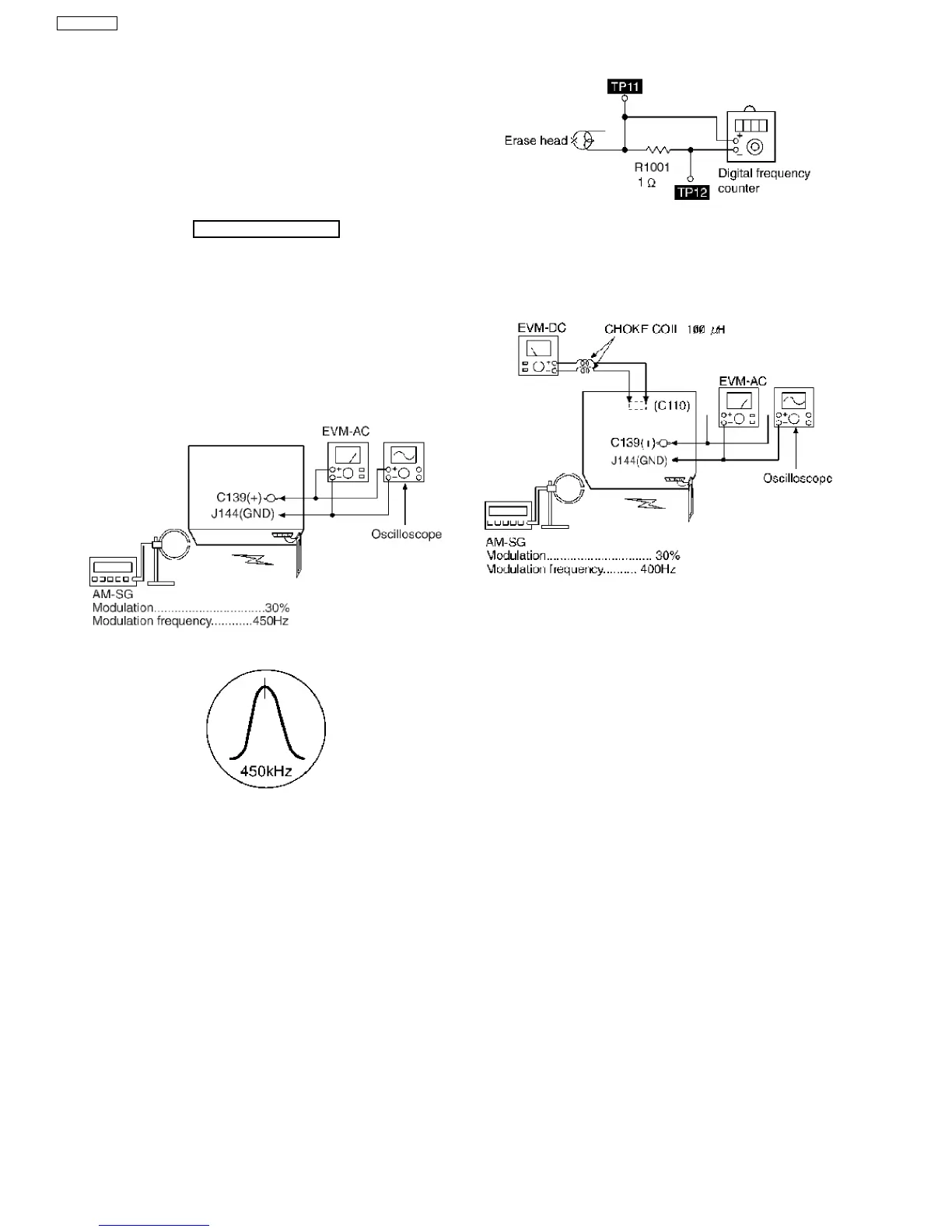
1. Connect the instrument as shown in Fig. 5.
2. Set the unit to AM mode.
3. Apply signal as shown in Fig. 5 from AM-SG.
4. Adjust Z102 so that the output frequency is maximized in
Fig. 6.
Fig. 5
Fig. 6
18.2.2. AM RF Adjustment
1. Connect the instrument as shown in Fig. 7.
2. Set the unit to AM mode.
3. Set AM-SG to 520kHz.
4. Receive 520kHz in the unit.
5. Adjust Z101 (OSC) so that the EVM-AC is maximized.
6. Set AM-SG to 600Hz.
7. Receive 600Hz in the unit.
8. Adjust Z101 (ANT) so that the EVM-SG is maximized.
9. Set AM-SG to 520kHz.
10. Receive 520kHz in the unit.
11. Adjust Z101 (OSC) so that the EVM-DC value is with
1.1±0.5V.
Fig. 4
Fig. 7
18.2. Tuner Section
18.2.1. AM-IF Alignment
56
SA-VK61DGS