12
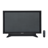
TH-152UX1 / TH-152UX1W / TH-152UX1C
How to distinguish the connector number when there are two or more boards
Board Name Function Board Name Function
A Digital Signal Processor, Microcomputer C1
(CA(C1), CE(C1),
CJ(C1), CN(C1))
Data Drive
DU Digital Processor
DN 3D Digital Signal Processor, Microcomputer
D
(D1-D4)
Format Converter, Plasma AI Processor
Sub-Field Processor
C2
(CB(C2), CF(C2),
CK(C2), CP(C2))
Data Drive
DS Slot Interface (Audio/ Video/ Sync InputSwitch),
DC-DC Converter
C3
(CC(C3), CG(C3),
CL(C3), CQ(C3)
Data Drive
SC
(SCU, SCD)
Scan Drive C4
(CD(C4), CH(C4),
CM(C4), CR(C4)
Data Drive
SU1
SU2
SU3
Scan Out (Upper) P(P), P(P1-P9) Power Supply
PSC Power Scan Supply
PSS
(PSS_L, PSS_R)
Power SUS Supply
SD1
SD2
SD3
Scan Out (Lower) F
(FA, FB, FC,FD, FE)
Filter
DSC Scan Signal Distribution F1 RELAY Control
SS
(SSU, SSD)
Sustain Drive F2 Filter Coupling
PB(PB1-PB4) Fan Control
SS2 Sustain Out (Upper) HX PC / RS-232C / LED Transmit
SS3 Sustain Out (Middle) HDE DVI-D Interface
SS4 Sustain Out (Lower) LVDS output
(Upper, Lower)
Front End LVDS output
DSS SUS Signal Distribution 4K input
(Upper, Lower)
Front End 4K input
V1 LED_G, R 2K input Front End 2K input
V2 Key switch POWER Front End Power
V3 Remote receiver EXTERIOR Front End Exterior
S1 Power Switch
example meaning
P-Board (P1-P9) 2P9 connector P9 on P2-Board
P-Board (P) P9 connector P9 on P-Board
D-Board (D1-D4) 2D36 connector D36 on D2-Board
F-Board (FA-FE) BF91 connector F91 on FB-Board
PB-Board (PB1-PB4) 3PB54 connector PB54 on PB3-Board
C-Board (C1-C4) C25CB connector C25 on C2(CB)-Board
PSS-Board (R, L) PSS6R connector PSS6 on PSS_R-Board
SC SS-Board (U D) SC2U connector SC2 on SCU-Board

 Loading...

