EasyManua.ls Logo

Panasonic TH-42PX600U

Panasonic TH-42PX600U
165 pages
To Next Page IconTo Next Page
Loading...
© 2006 Matsushita Electric Industrial Co., Ltd. All
rights reserved. Unauthorized copying and
distribution is a violation of law.
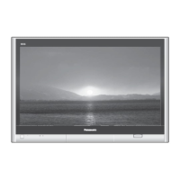
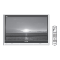
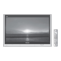
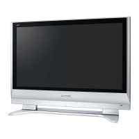
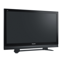
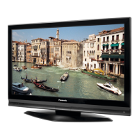
TH-42PX600U
GP9DU Chassis
Digital High Definition Plasma Television
Specifications
Power Source AC 120 V, 50/60 Hz
Power Consumption
Maximum 399 W
Standby condition 0.2 W (Without CableCARD
TM
)
14.0 W (With CableCARD
TM
)
Plasma Display panel
Drive method AC type
Aspect Ratio 16 : 9
Contrast Ratio (max) 10000 : 1
Visible screen size
(W × H × Diagonal)
(No. of pixels)
109 cmV
37.1 × 21.3 × 42.8 (944 mm × 542 mm × 1,088 mm)
786,432 (1,024 (W) × 768 (H)) [3,072 × 768 dots]
Sound
Speaker Woofer 3.2 (80 mm) × 2 pcs, 8 W
Speaker 0.9 × 4.0 (23 mm × 100 mm) × 2 pcs, 8W
Audio Output 31 W [13 W + 2.5 W, 13 W + 2.5 W] (10 % THD)
PC signals VGA, SVGA, XGA
SXGA (compressed)
Horizontal scanning frequency 31 - 69 kHz
Vertical scanning frequency 59 - 86 Hz
Channel Capability (Digital/Analog) VHF/UHF: 2 - 69, CATV: 1 - 135
Operating Conditions Temperature: 32 °F - 104 °F (0 °C - 40 °C)
Humidity: 20 % - 80 % RH (non-condensing)
Connection Terminals
INPUT 1-3 VIDEO: RCA PIN Type × 1 1.0 V [p-p] (75 W)
S-VIDEO: Mini DIN 4-pin Y: 1.0 V [p-p] (75 W) C: 0.286 V [p-p] (75 W)
AUDIO L-R: RCA PIN Type × 2 0.5 V [rms]
ORDER NO.MTNC060475CE
B19 Canada: B07

Table of Contents

Other manuals for Panasonic TH-42PX600U

Questions and Answers:

Panasonic TH-42PX600U Specifications

General IconGeneral
Screen Size42 inches
Display TechnologyPlasma
Resolution1024 x 768
Aspect Ratio16:9
Contrast Ratio10000:1
HDMI Ports2
Component Video Inputs2
S-Video Input1
Composite Input3
PC Input1
TunerATSC

Summary

Specifications

Power Source

Specifies the power requirements for the television.

Power Consumption

Details the power usage in different modes.

Plasma Display panel

Provides technical details about the plasma display.

Sound

Information about the audio output and speaker specifications.

PC signals

Lists supported PC signal types and frequencies.

Channel Capability (DigitalAnalog)

Specifies the supported channel ranges for digital and analog.

Operating Conditions

Details the required temperature and humidity for operation.

Connection Terminals

Lists available input terminals and their specifications.

Specifications (Continued)

Component, HDMI, and PC Inputs

Details various input signal types and their connection specifications.

Features List

Lists key features like 3D Y/C Filter, Closed Caption, V-Chip, etc.

Dimensions and Weight

Provides physical dimensions and weight for the TV with and without pedestal.

Applicable Signals

Input Signal Compatibility

Table detailing signal compatibility for Component, HDMI, and PC inputs.

Safety Precautions

General Servicing Guidelines

Essential guidelines to follow when servicing the unit.

Leakage Current Checks (Cold and Hot)

Procedures for checking leakage current with the unit unplugged and powered on.

Prevention of Electro Static Discharge (ESD)

ESD Prevention Techniques

Techniques to prevent damage to sensitive electronic components from static electricity.

Safety Caution

Important safety caution regarding ESD prevention during handling.

About Lead-Free Solder (PbF)

Lead-Free Solder Recommendations

Recommendations for types of lead-free solder suitable for repair work.

Service Hints and Board Identification

Board Functions Overview

Table mapping board names to their primary functions within the TV.

Plasma Panel Replacement: Initial Steps

Back Cover and Fan Removal

Steps to remove the rear cover and cooling fans.

Speaker Box Removal

Procedure for removing the left and right speaker assemblies.

Rear Terminal Cover Removal

Steps to remove the cover for the rear terminal connections.

Plasma Panel Replacement: Board Removal

P-Board, PA-Board, Tuner Unit, and DT-Board Removal

Detailed steps for removing the P-Board, PA-Board, Tuner Unit, and DT-Board.

Plasma Panel Replacement: Board Removal (Cont.)

DG-Board and H-Board Removal

Instructions for removing the DG-Board and H-Board.

Plasma Panel Replacement: Board Removal (Cont.)

HC, D, SU, and SD-Board Removal

Procedures for removing the HC, D, SU, and SD-Boards.

Plasma Panel Replacement: Board Removal (Cont.)

SC, SS, C1, and C2-Board Removal

Steps for removing the SC, SS, C1, and C2-Boards.

Plasma Panel Replacement: Component Removal

Front Bracket and Stand Bracket Removal

Steps to remove the front bracket and the left and right stand brackets.

G, GK, S-Board Removal

Procedure for removing the G-Board, GK-Board, and S-Board.

Plasma Panel Replacement: Panel Removal

GS-Board Removal

Detailed steps for removing the GS-Board.

Plasma Panel Section Removal

Procedure for safely removing the plasma panel assembly from the front frame.

Plasma Panel Replacement: Component Removal (Cont.)

Squawker Speaker and K-Board Removal

Instructions for removing the squawker speaker and K-Board.

Plasma Panel Replacement: Final Steps

Plasma Panel Installation

Final steps and precautions for installing the new plasma panel.

Caution Statements

Cable Connection Verification

General caution statement regarding cable connections and verification.

Location of Lead Wiring

Wiring Diagram (1)

Illustrates the routing and connection of specific wiring components.

Lead of Wiring (2)-1

Lead of Wiring (2)-2

Lead of Wiring (3)-1

Lead of Wiring (3)-2

Lead of Wiring (4)-1

Lead of Wiring (4)-2

Lead of Wiring (5)

Self-check Function Operations

Accessing Self-Check

Steps to access the self-check function using the remote and TV buttons.

Exiting Self-Check

Instructions on how to exit the self-check function.

Understanding Screen Display

Explains the meaning of the self-check screen display and error codes.

Self-Check Check Points

Power LED Blinking Timing Chart

LED Blinking Error Indications

Explains how LED blinking patterns identify defective blocks.

No Power Troubleshooting

Initial Check Points for No Power

Identifies the initial states of No Power indication by the power LED.

No Picture Troubleshooting

Drive Circuits LED Indicators

Identifies LED indicators on SC-Board and SS-Board for drive circuits.

Local Screen Failure Diagnosis

Serviceman Mode Operations

Entering Serviceman Mode

Steps to enter the Serviceman Mode using the remote control.

Serviceman Mode Navigation and Commands

Explanation of the key commands for navigating the Serviceman Mode.

Adjustment Mode Contents Overview

Lists the adjustable parameters, sample data, and remarks.

Memory Edit Mode Operations

Accessing Memory Edit Mode

Procedure to access the Memory Edit mode within the Serviceman Mode.

Exiting Memory Edit Mode

Instructions on how to exit the Memory Edit mode.

Device Data Mode Operations

Accessing Device Data Mode

Procedure to access device data display for market analysis.

Exiting Device Data Mode

Instructions on how to exit the Device Data mode.

Adjustment Procedures: Driver Set-up

Driver Set-up Steps

Steps for driver setup, including item preparation and adjustments.

Driver Voltage Adjustments

Details specific voltage adjustments for driver sections referring to panel data.

Initialization Pulse Adjust

Printed Circuit Board (PCB) Exchange

Caution for PCB Exchange

Warning regarding PCB exchange and discharge of capacitors.

Quick Adjustment After PCB Exchange

Steps for quick adjustments after replacing PCBs like P Board and SC Board.

Adjustment Volume and Test Point Locations

Adjustment Volume Location Diagram

Diagram showing the physical locations of adjustment volumes on various boards.

Test Point Location Diagram

Diagram indicating the locations of test points for voltage measurements.

White Balance Adjustment

Sub Bright Adjustment

ABL Operation Level Adjustment

ABL Adjustment Notes

Important notes regarding power fluctuations and DAC adjustment points.

Hotel Mode Setup

Hotel Mode Purpose

Explains the function of the Hotel Mode for restricting features.

Accessing Hotel Mode Menu

Steps to access the Hotel Mode setup menu.

Explain the Hotel Mode Setup Menu

Description of the various items and functions available within the Hotel Mode menu.

Conductor Views: P-Board

P-Board Foil Side View

Foil side view of the P-Board with component layout and grid references.

Conductor Views: P-Board (Cont.)

P-Board Component Side View

Component side view of the P-Board with IC, Transistor, and Volume locations.

P-Board Foil Side View

Foil side view of the P-Board with IC, Transistor, and Volume locations.

Conductor Views: P-Board (Cont.)

P-Board Component Side View

Component side view of the P-Board with component labels and grid references.

Conductor Views: PA-Board

PA-Board Foil Side View

Foil side view of the PA-Board with component locations and grid references.

Conductor Views: PA-Board (Cont.)

PA-Board Component Side View

Component side view of the PA-Board with component locations and grid references.

Conductor Views: H-Board

H-Board Foil Side View

Foil side view of the H-Board with component locations and grid references.

Conductor Views: H-Board (Cont.)

H-Board Component Side View

Component side view of the H-Board with component locations and grid references.

Conductor Views: G and GS-Boards

G-Board Views

Foil and component side views of the G-Board with component layout.

GS-Board Views

Foil and component side views of the GS-Board with component layout.

Conductor Views: GK, HC, K, and S-Boards

GK, HC, K, and S-Board Views

Foil and component side views of the GK, HC, K, and S-Boards.

Conductor Views: DG-Board

DG-Board Foil Side View

Foil side view of the DG-Board with component locations and grid references.

Conductor Views: DG-Board (Cont.)

DG-Board Component Side View

Component side view of the DG-Board with component locations and grid references.

Conductor Views: DT-Board

DT-Board Foil Side View

Foil side view of the DT-Board with component locations and grid references.

Conductor Views: DT-Board (Cont.)

DT-Board Component Side View

Component side view of the DT-Board with component locations and grid references.

Conductor Views: D-Board

D-Board Foil Side View

Foil side view of the D-Board with component locations and grid references.

Conductor Views: D-Board (Cont.)

D-Board Component Side View

Component side view of the D-Board with component locations and grid references.

Conductor Views: C1-Board

C1-Board Views

Foil and component side views of the C1-Board with component layout.

Conductor Views: C2-Board

C2-Board Views

Foil and component side views of the C2-Board with component layout.

Conductor Views: SC-Board

SC-Board Foil Side View

Foil side view of the SC-Board with component locations and grid references.

Conductor Views: SC-Board (Cont.)

SC-Board Component Side View

Component side view of the SC-Board with component locations and test points.

Conductor Views: SC-Board (Cont.)

SC-Board Component Side View

Component side view of the SC-Board showing component layout and connections.

Conductor Views: SU-Board

SU-Board Views

Foil and component side views of the SU-Board with component layout.

Conductor Views: SD-Board

SD-Board Views

Foil and component side views of the SD-Board with component layout.

Conductor Views: SS-Board

SS-Board Foil Side View

Foil side view of the SS-Board with component locations and grid references.

Conductor Views: SS-Board (Cont.)

SS-Board Component Side View

Component side view of the SS-Board with component layout and test points.

Schematic and Block Diagram Notes

Main Block Diagram

P-Board Block Diagram

P-Board (1 of 6) Schematic Diagram

P-Board (2 of 6) Schematic Diagram

P-Board (3 of 6) Schematic Diagram

P-Board (4 of 6) Schematic Diagram

P-Board (5 of 6) Schematic Diagram

P-Board (6 of 6) Schematic Diagram

PA-Board (1 of 2) Block Diagram

PA-Board (2 of 2) Block Diagram

PA-Board (1 of 3) Schematic Diagram

PA-Board (2 of 3) Schematic Diagram

PA-Board (3 of 3) Schematic Diagram

H-Board Block Diagram

H-Board (1 of 3) Schematic Diagram

H-Board (2 of 3) Schematic Diagram

H-Board (3 of 3) Schematic Diagram

G, GK, HC, K and S-Board Block Diagram

G-Board Schematic Diagram

GK, HC, K and S-Board Schematic Diagram

DG-Board (1 of 3) Block Diagram

DG-Board (2 of 3) Block Diagram

DG-Board (3 of 3) Block Diagram

DG-Board (1 of 8) Schematic Diagram

DG-Board (2 of 8) Schematic Diagram

DG-Board (3 of 8) Schematic Diagram

DG-Board (4 of 8) Schematic Diagram

DG-Board (5 of 8) Schematic Diagram

DG-Board (6 of 8) Schematic Diagram

DG-Board (7 of 8) Schematic Diagram

DG-Board (8 of 8) Schematic Diagram

DT and GS-Board Block Diagram

DT-Board (1 of 7) Schematic Diagram

DT-Board (2 of 7) Schematic Diagram

DT-Board (3 of 7) Schematic Diagram

DT-Board (4 of 7) and GS-Board Schematic Diagram

DT-Board (5 of 7) Schematic Diagram

DT-Board (6 of 7) Schematic Diagram

DT-Board (7 of 7) Schematic Diagram

D-Board Block Diagram

D-Board (1 of 6) Schematic Diagram

D-Board (2 of 6) Schematic Diagram

D-Board (3 of 6) Schematic Diagram

D-Board (4 of 6) Schematic Diagram

D-Board (5 of 6) Schematic Diagram

D-Board (6 of 6) Schematic Diagram

C1 and C2-Board Block Diagram

C1-Board (1 of 2) Schematic Diagram

C1-Board (2 of 2) Schematic Diagram

C2-Board (1 of 2) Schematic Diagram

C2-Board (2 of 2) Schematic Diagram

SC, SU and SD-Board Block Diagram

SC-Board (1 of 2) Schematic Diagram

SC-Board (2 of 2) Schematic Diagram

SU-Board (1 of 2) Schematic Diagram

SU-Board (2 of 2) Schematic Diagram

SD-Board (1 of 2) Schematic Diagram

SD-Board (2 of 2) Schematic Diagram

SS-Board Block Diagram

SS-Board Schematic Diagram

Parts Location and Mechanical Replacement Parts List

Parts Location Diagrams

Diagrams showing the physical locations of various components on the TV.

Packing Exploded Views

Mechanical Replacement Parts List

Electrical Replacement Parts List Notes

Electrical Replacement Parts List (Continuation)

Electrical Replacement Parts List (Continuation)

Electrical Replacement Parts List (Continuation)

Electrical Replacement Parts List (Continuation)

Electrical Replacement Parts List (Continuation)

Electrical Replacement Parts List (Continuation)

Electrical Replacement Parts List (Continuation)

Electrical Replacement Parts List (Continuation)

Electrical Replacement Parts List (Continuation)

Electrical Replacement Parts List (Continuation)

Electrical Replacement Parts List (Continuation)

Electrical Replacement Parts List (Continuation)

Electrical Replacement Parts List (Continuation)

Electrical Replacement Parts List (Continuation)

Electrical Replacement Parts List (Continuation)

Electrical Replacement Parts List (Continuation)

Electrical Replacement Parts List (Continuation)

Electrical Replacement Parts List (Continuation)

Electrical Replacement Parts List (Continuation)

Electrical Replacement Parts List (Continuation)

Electrical Replacement Parts List (Continuation)

Electrical Replacement Parts List (Continuation)

Electrical Replacement Parts List (Continuation)

Electrical Replacement Parts List (Continuation)

Electrical Replacement Parts List (Continuation)

Electrical Replacement Parts List (Continuation)

Electrical Replacement Parts List (Continuation)

Electrical Replacement Parts List (Continuation)

Electrical Replacement Parts List (Continuation)

Electrical Replacement Parts List (Continuation)

Electrical Replacement Parts List (Continuation)

Related product manuals