User Manual For Cyclone LC Programmers 12
If power is provided via the Cyclone, the user may need to configure the programming image
accordingly. Image creation and configuration is discussed in Section 2.3 - Creating A Stand-Alone
Programming Image.
For more information on the various power configurations, the user should refer to their Cyclone’s User
Manual. There is a also a blog post that covers this topic at: http://www.pemicro.com/blog/
index.cfm?post_id=121
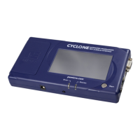
Step 2. Connect Cyclone to a PC (for programming image setup)
The Cyclone programmer should be connected to the PC via USB, Serial, or Ethernet. Cables for each
of these options are included with the Cyclone.
Note: An Ethernet connection requires IP setup on the Cyclone unit; please refer to the Cyclone’s User
Manual for more information.
Step 3. Connect Cyclone to target
A ribbon cable should be connected from the appropriate Cyclone header (located under the Cyclone’s
access panel) to the header for your target device. Ribbon cables are provided with the Cyclone.
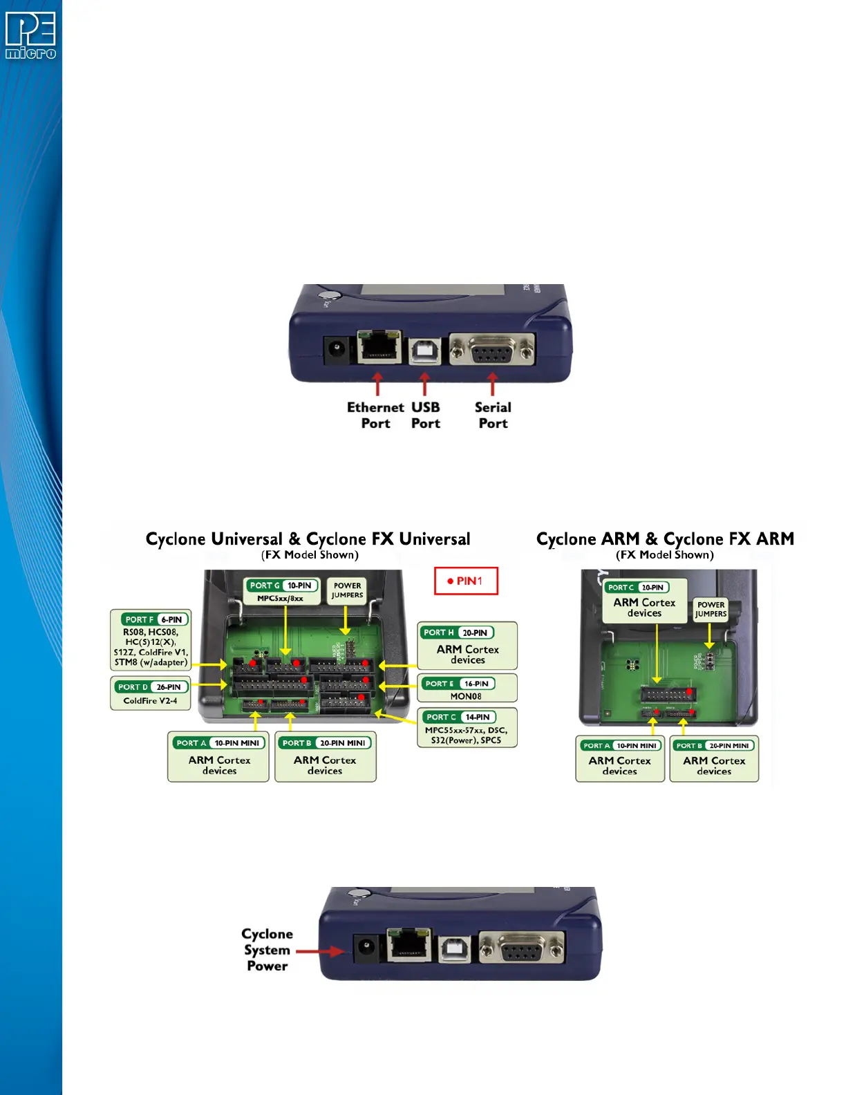
Step 4. Plug in power to the Cyclone
The provided power supply should be plugged into the System Power jack of the Cyclone programmer.
Other power connections should be made according to the power configuration selected in Step 1.
On power-up the user may need to agree to a firmware update on the Cyclone unit.
 Loading...