User Manual For Cyclone LC Programmers 19
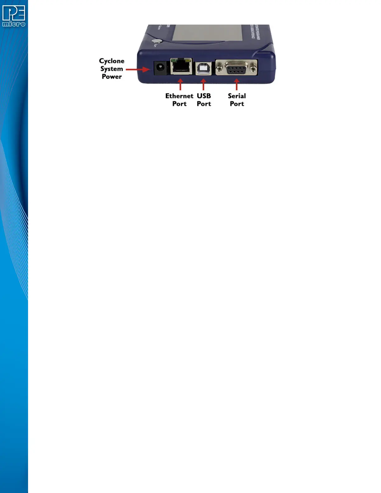
Figure 3-2: Cyclone LC Right Side View
3.5 Cyclone System Power
The Cyclone LC programmer requires a regulated 6V DC Center Positive power supply with 2.5/
5.5mm female plug. Cyclones derive power from the Power Jack located on the right end of the
unit. The location of Cyclone System Power is shown in Figure 3-2.
3.6 RS232 Communication (Serial Port)
The Cyclone LC provides a DB9 Female connector to communicate with a host computer through
the RS232 communication (115200 Baud, 8 Data bits, No parity, 1 Stop bit). The location of the
Serial Port is shown in Figure 3-2.
3.7 Ethernet Communication
The Cyclone LC provides a standard RJ45 socket to communicate with a host computer through
the Ethernet Port (10/100 BaseT). The location of the Ethernet Port is shown in Figure 3-2.
3.8 USB Communications
The Cyclone LC provides a USB connector for Universal Serial Bus communications between the
Cyclone and the host computer. The Cyclone LC is a USB 2.0 Full-Speed compliant device. The
location of the USB Port is shown in Figure 3-2.
3.9 Electromechanical Relays
Inside the Cyclone LC programmer, two electromechanical relays are used to cycle target power.
The specifications of the relays are as following:
Maximum switched power: 30W or 125 VA
Maximum switched current: 1A
Maximum switched voltage: 150VDC or 300VAC
UL Rating: 1A at 30 VDC
1A at 125 VAC
PEmicro only recommends switching DC voltages up to 24 Volts.
 Loading...