User Manual For Cyclone LC Programmers 24
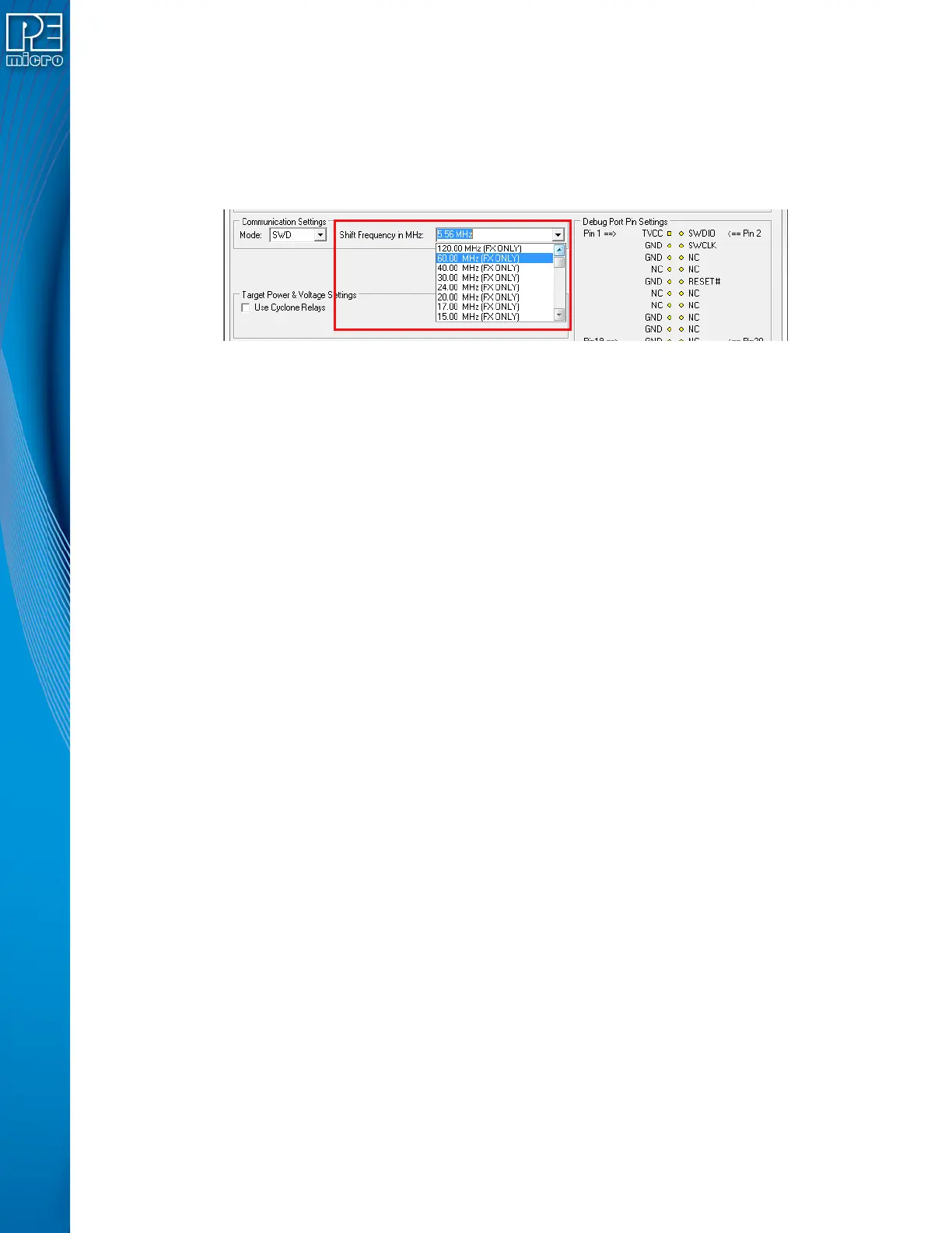
3.17.1.2.1 High-Performance Communications (FX ONLY)
If high-performance options are available for the selected device they will appear in the “Shift
Frequency in MHz” drop-down. Cyclone FX programmers are capable of high-performance
communications when using certain ARM Cortex targets in SWD mode.
Note: Cyclone LC programmers cannot currently take advantage of high-performance options, although
the frequencies appear in the display.
Figure 3-9: High-Performance Options (FX ONLY)
3.17.2 PORT B: 20-Pin Keyed Mini Connector (Kinetis, S32 (ARM), other PEmicro-Supported ARM
devices)
3.17.2.1 JTAG Mode Pin Assignments
The Cyclone provides a keyed 20-pin 0.050-inch pitch double row connector for ARM targets. The
location of the this header is indicated as PORT B in Figure 3-5. The 20-pin keyed mini connector
pin definitions for JTAG mode are as follows:
20-Pin Keyed Mini Connector JTAG Mode Pin Assignments
PIN 1 - TVCC TMS - PIN 2
PIN 3 - GND TCK - PIN 4
PIN 5 - GND TDO - PIN 6
PIN 7 - NC TDI - PIN 8
PIN 9 - NC* RESET - PIN 10
PIN 11 - NC NC* - PIN 12
PIN 13 - NC NC* - PIN 14
PIN 15 - GND NC* - PIN 16
PIN 17 - GND NC* - PIN 18
PIN 19 - GND NC* - PIN 20
Note: *The pin is reserved for internal use within the PEmicro interface.
3.17.2.2 SWD Mode Pin Assignments
Cyclone LC programmers also support SWD Mode. This replaces the JTAG connection with a
clock and single bi-directional data pin.
20-Pin Keyed Mini Connector SWD Mode Pin Assignments
PIN 1 - TVCC TMS/SWDIO - PIN 2
PIN 3 - GND TCK/SWCLK - PIN 4
PIN 5 - GND NC* - PIN 6
PIN 7 - NC NC* - PIN 8
PIN 9 - NC* RESET - PIN 10
PIN 11 - NC NC* - PIN 12
PIN 13 - NC NC* - PIN 14
PIN 15 - GND NC* - PIN 16
PIN 17 - GND NC* - PIN 18
PIN 19 - GND NC* - PIN 20
Note: *The pin is reserved for internal use within the PEmicro interface.
 Loading...