Esprit 728 Ultra & 738 Ultra 9
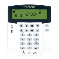
2.11.2 N.C. Contacts, Without EOL Resistor, With Tamper Recognition, ATZ Series
If your security installation requires tamper recognition and you are using the ATZ feature, connect the detection
devices and program the control panel as shown in Figure 17. Do not use devices with normally open contacts, as this
will cause the zone to remain open. This setup will communicate the status of each zone to the control panel (see
Figure 15 on page 8) and display open zones on the keypad. The control panel will also communicate any detected
tampers (cuts) on the system as per Tamper/Wire Fault Recognition Options on page 38.
Figure 17: N.C. Contacts, without EOL Resistor, with Tamper Recognition
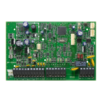
2.11.3 N.C. Contacts, With EOL Resistor, With Tamper & Wire Fault Recognition (UL/cUL), ATZ Series
If your system requires tamper (cut) and wire fault (short) recognition, connect two detection devices to one input
terminal with a 1k9 end of line (EOL) resistor and program the control panel as shown in Figure 18. Do not use
devices with normally open contacts, because this will cause the zone to remain open. This setup will communicate the
status of each zone to the control panel (see Figure 18) and display open zones on the keypad. Any tampers (cuts)
and/or wire fault (shorts) detected on the system are communicated as per Tamper/Wire Fault Recognition Options on
page 38.
Figure 18: N.C. Contacts, with EOL Resistor, with Tamper and Wire Fault Recognition (UL/cUL)
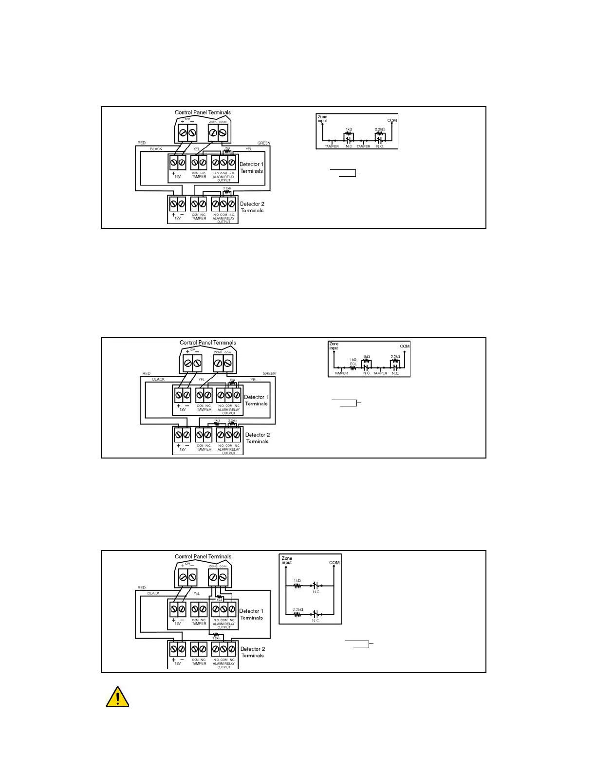
2.11.4 N.C. Contacts, With ATZ Parallel Wiring
If your security installation does not require tamper or wire fault recognition, but requires the connection of two
detection devices to one input to be in parallel, connect the devices and program the control panel as shown in ATZ
Parallel Wiring on page 9. Do not use devices with normally open contacts as this will cause the zone to remain open.
This setup will communicate the status of each zone to the control panel (see Figure 19 on page 9) and display open
zones on the keypad. For more information, see ATZ Parallel Wiring on page 27.
Figure 19: ATZ Parallel Wiring
Address 090, key [7] (see ATZ Parallel Wiring on page 27) must be ON in order to connect the zones in
parallel.
Address 088, [MEM] = ON (EOL resistor disabled)
[0] =
[STAY] =
Address 090, [7] = OFF (ATZ wiring in series)
[8] = ON (ATZ enabled)
Refer to section 10.7 on page 38.
Address 088, [MEM] = OFF (EOL resistor enabled)
[0] =
[STAY] =
Address 090, [7] = OFF (ATZ) wiring in series)
[8] = ON (ATZ enabled)
Refer to section 10.7 on page 38.
Address 088, [0] = OFF
[
STAY] = OFF
Address 090, [7] = ON (ATZ wiring in parallel)
[8] = ON (ATZ enabled)
Tamper/Wire Fault disabled