10 Reference & Installation Manual
2.12 Fire Circuit
If your security installation requires the use of smoke detectors, define zone 3 as a 24Hr fire zone. When zone 3 is defined as
24Hr, it becomes a 4-wire smoke detector fire zone (2-wire smoke detector support must be disabled, address 086 key [
BYP] =
OFF). If using 2-wire smoke detectors and ATZ is enabled, zone 3 can be defined as 24Hr (728 Ultra only). Please refer to 24Hr
and 4-Wire Smoke Detector Fire Zones on page 28.
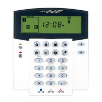
2.12.1 4-Wire Smoke Detector Connections (Standard Installation)
Connect the 4-wire smoke detectors to zone 3 as shown in Figure 20. Note that a fire zone must
use a 1k9 EOL resistor. If there is a line short or if the smoke detector becomes active, whether
the system is armed or disarmed, the control panel will generate an alarm. If the line is open, the
control panel will send a fire loop trouble report to the monitoring station and the trouble
indicator ([
STAY] key) will illuminate or a trouble will appear in the keypad’s trouble display.
All smoke detectors must be connected using a daisy chain configuration.
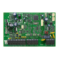
2.12.2 4-Wire Smoke Detector Connections (UL/cUL Installation)
For UL/cUL installations, use a 4-wire, latching, smoke detector (System Sensor model
2112/24D). To supervise the power supply, install an end of line relay (Model MR3).
Connect the smoke detectors and relay as shown in Figure 21. In the event that power is
interrupted, the relay will generate a fire trouble report (see 24Hr and 4-Wire Smoke
Detector Fire Zones on page 28).
To reset (unlatch) the smoke detectors after an alarm, momentarily interrupt power to the
detectors. To do so, verify that the negative (-) of the smoke detectors is connected to a
PGM. Set the PGM for Timed N.C. (normally closed), and program the PGM to open when
any two keys on the keypad are pressed simultaneously. For more information on
programming the PGM, see PGMs (Programmable Outputs) on page 35.
Example: To program the PGM to conduct a 30-second smoke detector reset when the
[
CLEAR] and [ENTER] keys are pressed at the same time (see PGMs (Programmable
Outputs) on page 35):
Address 039 = [BYP] [2ND] Address 042 = [2ND] [6]
Address 040 = [5] [0] Address 056 = [0] [3] [0]
All smoke detectors must be connected using a daisy chain configuration.
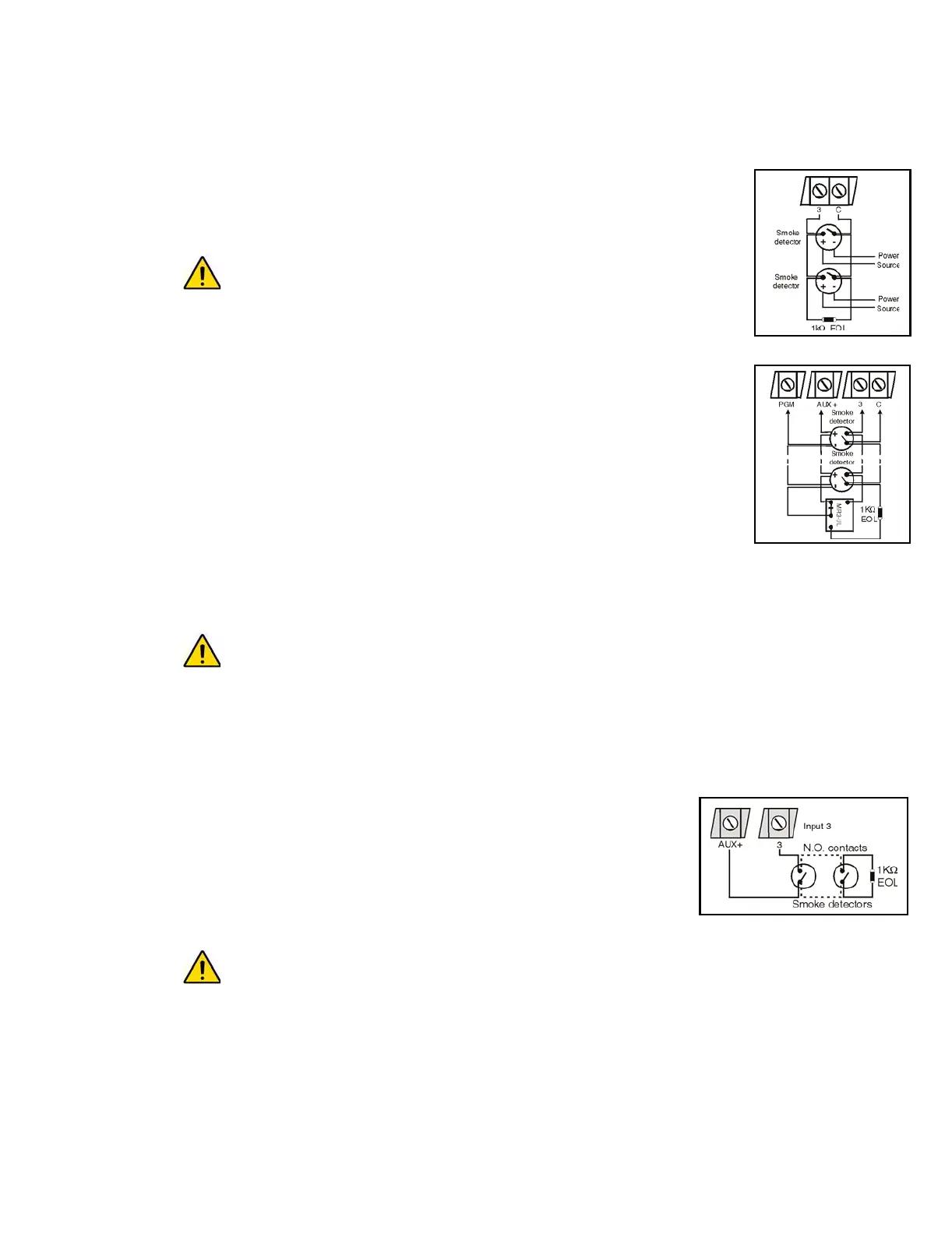
2.12.3 2-Wire Smoke Detector Connections
Connect the 2-wire smoke detectors to input 3 as shown in Figure 22. Note that a fire zone must use a 1k9 EOL resistor.
If there is a line short or if the smoke detector becomes active, whether the system is armed or disarmed, the control
panel will generate an alarm. If the line is open the control panel will send a fire loop trouble report to the monitoring
station and the trouble indicator ([
STAY] key) will illuminate or a trouble will appear in the keypad’s trouble display.
With the 728 Ultra, when ATZ is disabled, the 2-wire smoke detector will be
connected to zone 3 (which is assigned to input 3). When ATZ is enabled, the 2-
wire smoke detector will be connected to zone 5 (which is assigned to input 3 as
shown in Figure 15 on page 8; 728 Ultra only). Zone 4 (zone 11 for 738 Ultra) will
be disabled automatically to prevent the control panel from generating a “fire
loop” trouble. Enable address 086, key [
BYP] to configure the control panel to
recognize the 2-wire smoke detector connected to input 3.
To conduct a 30-second reset, press and hold the [CLEAR] and [ENTER] keys on
any keypad for 3 seconds.
All smoke detectors must be connected using a daisy chain configuration.
The 728 Ultra and 738 Ultra control panels support a maximum of five 2-wire smoke detectors.
UL Warnings. For UL/cUL installations:
- The operating voltage of the fire circuit must be between 11 to 12Vdc.
- Use only the Hochicki model SLR 835BH-2 2-wire smoke detector.
- 2-wire smoke detectors of different models other than the Hochicki model are not to be used.
2.13 Serial Output Connector
The four-pin Serial Output Connector is used to connect additional external devices to the control panel. To use the output
connector, the PGM (PGM1 for 738 Ultra) must be disabled. To disable the PGM, program [2
ND] [2ND] into addresses 039, 040
and 042 (addresses 040 and 042 for 738 Ultra). For serial output connector specifications, refer to Specifications on page 1.
Figure 20
Figure 21
Figure 22
 Loading...