S
PECTRA
1759EX
9
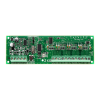
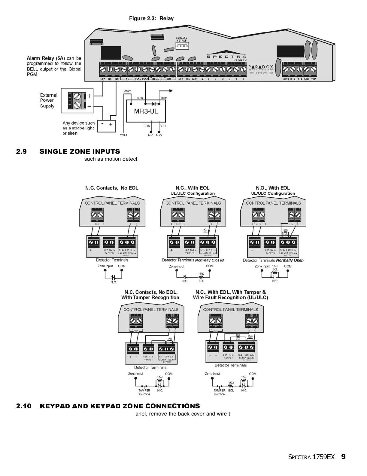
Figure 2.3: Relay and PGM Connections
2.9 SINGLE ZONE INPUTS
Detection devices such as motion detectors and door contacts are connected to the control panel's zone input terminals. Figure
2.4 (below) demonstrates single zone input terminal connections recognized by Spectra. Once connected, the associated zone's
parameters must be defined. For details refer to Zone Programming on page 16.
Figure 2.4: Single Zone Input Connections
2.10 KEYPAD AND KEYPAD ZONE CONNECTIONS
To connect the keypads to the control panel, remove the back cover and wire the GRN, YEL, RED, and BLK terminals of each
keypad to the corresponding terminals on the control panel as shown in Figure 2.2 on page 7. There is no limit to the number of
keypads that can be connected to the control panel so long as the current consumption does not surpass 700mA. For details on
Keypad Tamper Supervision see section 11.8 on page 42.
AUX+ or External Power Supply.
See Programmable Output
Connections on page 8
 Loading...