OWOUT - BASIC Stamp Command Reference
Page 210 • BASIC Stamp Programming Manual 2.0b • www.parallaxinc.com
The third part, the Memory Function Command, allows the BASIC Stamp
to address specific memory locations, or features, of the 1-wire device.
Refer to the 1-wire device's data sheet for a list of the available Memory
Function Commands.
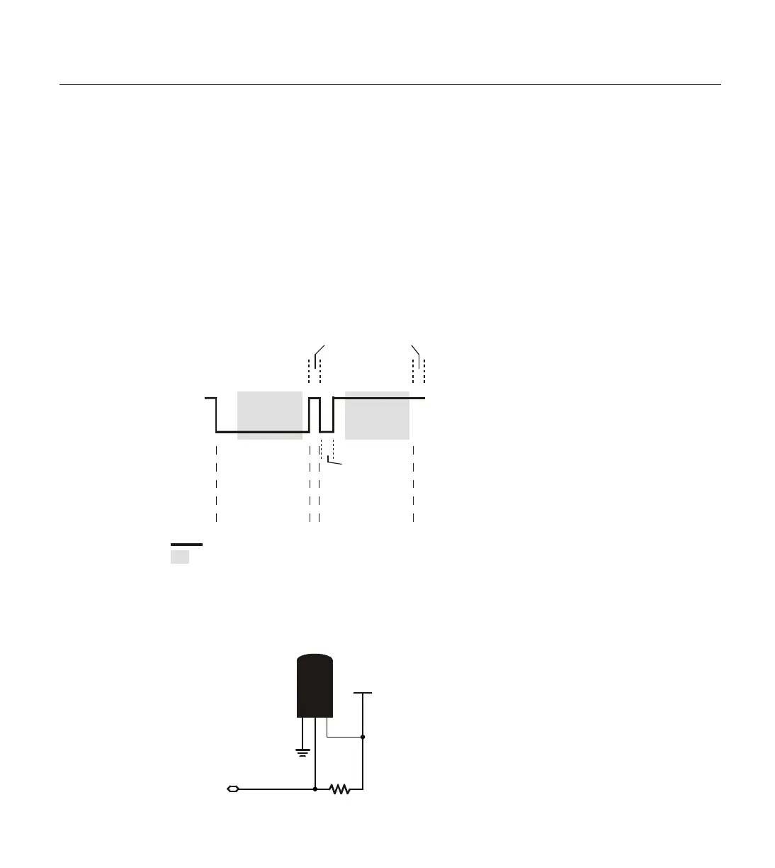
Finally, the Transaction/Data section is used to read or write data to the
1-wire device. The OWOUT command will write data at this point in the
transaction. A write is accomplished by generating a low-pulse of a
varying width to indicate a 0 or a 1. This is called a "Write Slot" and must
be at least 60
µs wide. Figure 5.23 shows typical Write Slots performed by
the BASIC Stamp. See the OWIN command for information on Read Slots.
The Demo Program uses a Dallas Semiconductor DS1820 Digital
Thermometer device connected as follows. Note that the 4.7 k
Ω pull-up
resister is required for proper operation.
Figure 5.24: DS1820 Circuit.
NOTE: The 4.7 k
Ω resister is
required for proper operation.
Vss
Vdd
P0
DS1820
(PR35)
4.7 k
Ω
DQ
1 2 3
Figure 5.23: Example Write Slots.
BASIC Stamp’s
Write “0” Slot
Apx. 72 s
µ
Apx 8 s
µ
+5 (vdd)
0 (vss)
BASIC Stamp’s
Write “1” Slot
Apx. 72 s
µ
Apx 8 s
µ
driven by BASIC Stamp
time when 1-wire device samples line (apx 15 - 45 s)
µ