Introduction to the BASIC Stamps
Page 26 • BASIC Stamp Programming Manual 2.0b • www.parallaxinc.com
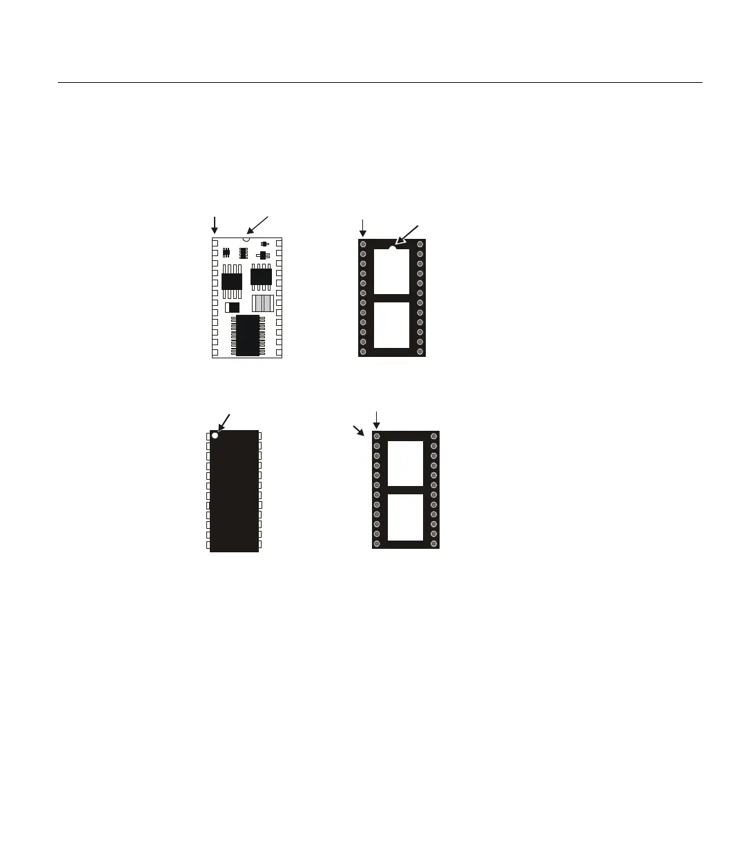
pin on the upper left of the device. The socket that accepts
this 24-pin module also has a half-circle or notch on one
end, indicating the correct orientation. See Figure 1.21 for
other examples.
BASIC Stamp Programming Connections:
Parallax, Inc. suggests using the cables provided in the BASIC Stamp
Starter Kit for programming the BASIC Stamps. When those cables are
not available, you may create your own by duplicating the following
diagrams in your cables and circuits.
Be very careful to follow these diagrams closely; it is quite common for
programming problems with the BASIC Stamps to be a result of a poorly
made custom cable or programming connections on your applications
board. With the BS2, BS2e, BS2sx and BS2p programming connections, it
is possible to reverse a couple of wires and still get positive results using
some of the "connection" tests our Tech. Support team tries and yet you
Figure 1.20: Pin 1 Indicators BS2-
IC shown in the correct orientation
in relation to a 24-pin socket.
Half-Circle
(Pin 1 indicator)
Pin 1
Half-Circle
(Pin 1 indicator)
here
“1” printed on PC board
(Pin 1 indicator)
here
1
“Dot”
(Pin 1 indicator)
Figure 1.21: Additional Examples
of Pin 1 Indicators (chip and
socket shown in the correct
orientation in relation to each other)