1: Introduction to the BASIC Stamps
BASIC Stamp Programming Manual 2.0c • www.parallaxinc.com • Page 27
still will not be able to communicate with the BASIC Stamp. It is vital that
you check your connections with a meter and verify the pin numbering to
avoid problems like this.
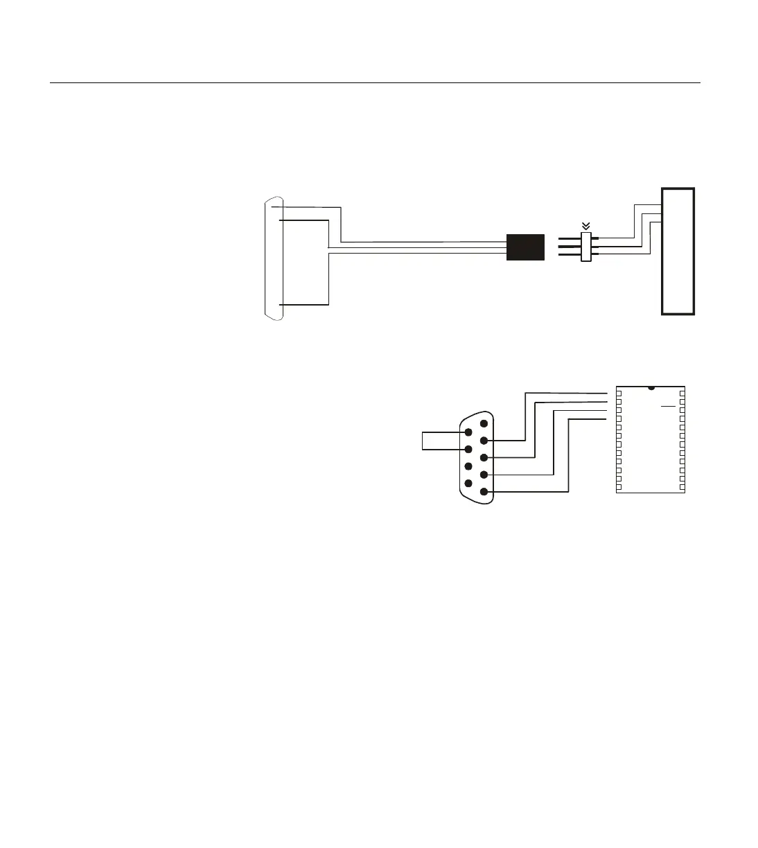
25 GND
11 BUSY
1 VIN
2 VSS
3 PC0
4 PCI
5 VDD
6 RES
7 P0
8 P1
9 P2
10 P3
11 P4
12 P5
13 P6
14 P7
P
C
P
A
R
A
L
L
E
L
P
O
R
T
BS1-IC
°
°
°
°
°
°
°
°
°
°
°
°
°
°
°
°
°
°
°
°
°
°
°
°
°
2 DO
Note: The Parallel port is
a 25-pin female connector,
usually on the back of the
computer.
Connect DSR and RTS for
automatic port detection.
SOUT
SIN
ATN
VSS
P0
P1
P2
P3
P4
P5
P6
P7
1
2
3
4
6
5
7
9
8
DSR
RTS
BS2-IC
Module
PC Serial Port
1
2
3
4
5
6
7
8
9
10
11
12
24
23
22
21
20
19
18
17
16
15
14
13
VIN
VSS
RES
VDD
P15
P14
P13
P12
P11
P10
P9
P8
Rx
Tx
DTR
GND
Note: The serial port is a 9-pin, or 25-pin, male
connector, usually on the back of the computer.
Use a 25-pin to 9-pin adapter when trying to
interface to a 9-pin cable.
Figure 1.22: BS1 Programming
Connections. Note: Though it is
connected to the BS1 to program it.
Figure 1.23: BS2, BS2e, BS2sx
and BS2p Programming
Connections. Note: Though it is
not shown, power must be
connected to the BASIC Stamp to
program it. Also, the programming
connections are the same for the