PGC, Inc 500-1000 CFM Air Handler May 2006
Appendix A A-2
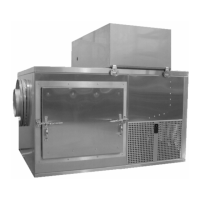
SYSTEM CONSTRUCTION
The 500-1000 CFM Conditioner consists of four main sections:
1. Conditioning Compartment: spray bypass damper, blower, spray eliminators, spray
jets, water sump, low water level safety float switch, process water float valve, stirring
jet, evaporator coil, and particulate filter
2. Mechanical Compartment (side access panels): refrigeration condenser, compressor,
receiver, , high- and low-pressure safety switches, filter/dryer, hot gas bypass valve,
water pump, water heater, water RTD, Programmable Logic Controller (PLC), and power
panel with terminal strips, circuit breakers, motor starter, and contactors
3. Conditioner Exterior: sump drain valve, air bypass damper actuator, UV filter, and air
temperature safety thermostat.
4. Control Enclosure: SmartPad™ user interface and optional chart recorder.
The unit is sturdily constructed, with a stainless steel interior and exterior, and insulated door
with heavy refrigerator-type latches and vapor-resistant seals. Double walls separated by
insulation are used around the conditioning chamber. All internal seams are welded to preclude
saturation of the insulation.
The spray tree is a 3” stainless steel tube (spray header) with spray nozzles attached along the
sides, and a clamp on each end for sealing the tube. The clamp on the right end secures a blank
plate against an O-ring gasket. A UV lamp is inserted from the electrical compartment, through
the plate on the left end.