PGC, Inc 500-1000 CFM Air Handler May 2006
Appendix A A-18
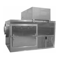
11. Install the quartz tube o-ring, S/S retaining washer and the blue, aluminum gland nut. Do
not over tighten the gland nut or the quartz tube will crack.
12. Install the new UV lamp and connect the wiring harness. The rubber boot on the wiring
harness will secure the lamp in the quartz tube.
A
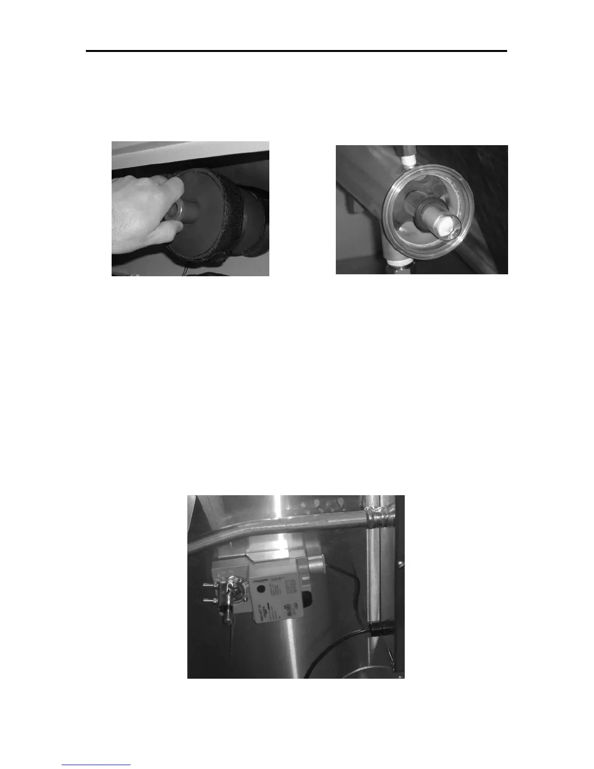
UTOMATIC DAMPER MOTOR ADJUSTMENTS
The damper actuator is designed to rotate a full 90°C, which may be more than necessary for the
air bypass damper on this unit. To accommodate for the limited movement of the damper, the
mechanical stops (Philips screws) on the actuator shaft are adjusted to reduce the operation range
of the motor.
After the stops are adjusted the actuator must be acclimated. This is an initialization procedure
that informs the actuator where the physical stops are located. To perform the acclimation
process remove the control input signal from PLC1 to the damper actuator. Then, while the
input signal is disconnected, press the clutch on the actuator two times. The motor will then cycle
to both stops. After the cycle is complete, re-connect the input signal.
Figure A-6 – Remove the gland nut Figure A-5 – Spray header with solid cap removed.
(quartz tube support bracket exposed)
Figure A-12 – Air Bypass Damper Actuator