PGC, Inc 500-1000 CFM Air Handler May 2006
Appendix A A-5
NOTE
In Slow Damper mode, the position of the damper is load dependent; the damper
will change slowly to achieve the desired conditions. The damper will also change
position in order to compensate for droop or overshoot in the air temperature
control loop.
W
ATER FLOW
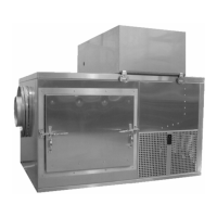
The water pump is located in the right section of the cabinet (accessible through the front or side
access doors). The water is picked up by the pump and heated, and then forced across the water
temperature sensor (100Ω platinum RTD) and into the spray header in the spray chamber. The
spray header is situated to spray water across air stream. The remainder of the water passes
through the particulate filter to remove debris.
T
EMPERATURE CONTROLS
The water temperature is sensed immediately prior to entering the spray headers, and the air &
humidity are measured by the HygroClip™ T/Rh transmitter that is located in the air stream.
The air heaters are positioned in the air-stream path between the chamber and the saturator. The
amount of heat applied is controlled by the dry-bulb control system with the sensing element in
the air stream. The duty cycle (the percentage of heat applied) for the air heater can be accessed
from the SmartPad™.
The water in the sump is cooled by the refrigeration evaporator, and is then sprayed across the air
stream to cool and saturate the air. Since the refrigeration system has a greater capacity than is
needed for most conditions, a hot gas bypass valve is provided to modulate the refrigeration
capacity as required. This valve is automatically adjusted by an actuator operating on a control
signal derived from the duty cycle of the water temperature control loop; the more the hot gas
valve opens, the more the refrigeration capacity is reduced. The relative position of the hot gas
bypass valve is represented by the water heater output percentage: Zero (0%) out is full
refrigeration capacity (hot gas bypass valve closed); one hundred percent (100%) out is minimum
refrigeration capacity (hot gas bypass valve open).
There are four factors that limit or control Water Set Point:
1. Humidity Control Band
Water Set Point will change in order to control Rh. If the measured Rh value is less
than the Rh set point, the Water Set Point will increase in order to increase the Rh by
increasing the dew point. The maximum rate at which the Water Set Point will
change is adjustable; the most common Water Set Point Rate of Change is
0.25ºC/minute (the maximum value). The Water Set Point Rate of Change is
proportional to the deviation from Rh Set Point. For example, if the Rh control band
is +/- 10% and the measured Rh is 10% below Set Point (at 100% of the control
bandwidth), the water Set Point will change at the rate of 0.25°C/minute (the
maximum Rate of Change X 100%). If the measured Rh is 5% below the Rh Set
Point (at 50% of the control bandwidth), the water Set Point will change at the rate of
0.125ºC/minute (the maximum rate of change X 50%).