PGC Inc. Horizontal 500-1000 CFM June 2006
Parameter Generation and Control, Inc.
4
Inspection
If the equipment is damaged upon receipt, immediately request the delivering carrier to
perform an inspection and prepare a report. All claims for damage must be made against
the delivering carrier. Report the nature and extent of the damage to PGC, 828-669-8717,
and include instrument serial and catalog numbers to facilitate repair or replacement.
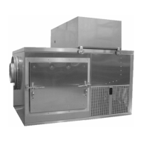
Installation
The 500-1000 CFM Conditioner was designed to be located adjacent to or on top of the
chamber to be conditioned. Allow at least 36 inches on the right side and front of the unit
for service. The location must be convenient to an adequate process water supply, drains
and electrical power. The conditioner must be reasonably level for proper water level
control.
Electrical power and water must be connected to this unit prior to operation. The required
voltage and current are listed on the nameplate located on the unit. The sump drain may
be connected directly to a facility drain, but the condensate drain must be connected to an
open (vented) trapped drain (see Figure 3) to ensure that backpressure on the facilities’
drain does not prevent proper drainage.
Note
The condensate drain has been supplied with a copper trap.
Plumbing
CAUTION
To prevent damage to the water pump and water heater, the unit must not
be operated until water is supplied to the unit and the sump has filled to the
proper level.
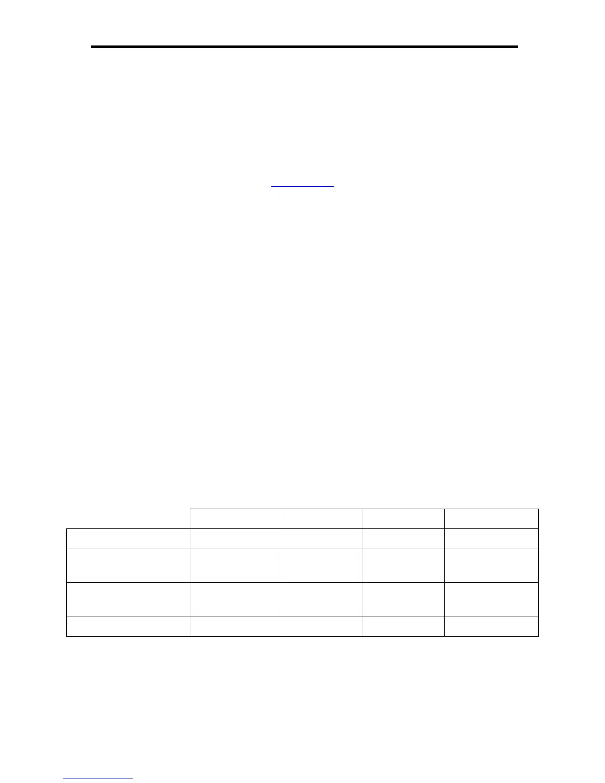
Process Water Supply Specifications
Units Maximum Typical Minimum
Process Water Pressure PSIG (Bar)
125 (8.6) N/A 5 (0.35)
Process Water Daily
Consumption
Gallons (Liters)
5.0 (19) 1.5 (5.7) 0 (0)
Condensate Production
per Day
Gallons (Liters)
5.0 (19) 1.5 (5.7) 0 (0)
Sump Water Volume Gallons (Liters)
15 (57) 15 (57) 6.6 (25)
Process Water Inlet
Connect a clean water supply line through an external customer-supplied hand valve to
the Process Water Inlet connection on the rear of the conditioner; this is a ½” male NPT
connection.