PGC, Inc 500-1000 CFM Air Handler May 2006
Appendix A A-10
Over Temperature Thermostat An air over-temperature safety
thermostat has been incorporated into the chamber. The temperature
adjustment for this device is located at the rear of the unit, on the side of
the heater housing. This safety thermostat is designed to protect the
contents of the test chamber from excessive temperature rise in the event
of a system failure. The operator may set this manually to protect the
product under test, normally 2-3°C (5°F) degrees above highest test
temperature. If this thermostat opens due to excessive temperature, the
chamber will shut down and the SmartPad™ user interface will indicate
“TEMPERATURE FAULT SET”. The thermostat will automatically
reset when the temperature inside the chamber drops below the cut-out
temperature. After the thermostat has reset, the SmartPad™ user interface
will indicate “TEMPERATURE FAULT CLEAR”, and the system may
be restarted by pressing the Standby key on the SmartPad™ key pad.
Low-Water Safety Switch A low-water level safety float
switch is located in the front left corner of the sump, near the
floor of the sump; this switch will shut down the air handler if the
water level in the sump falls below a safe operating level. If this
float switch opens, the air handler will shut down. The
SmartPad™ user interface will indicate “LOW WATER FAULT
SET”. The float switch will automatically reset when the water
level in the sump returns to a safe operating level. After the
switch has reset, the SmartPad™ user interface will indicate
“LOW WATER FAULT CLEAR”, and the system may be
restarted by pressing the Standby key on the SmartPad™ key
pad.
Blower Motor Thermal Contact The blower motor is
equipped with a contact that will open if the blower motor
temperature exceeds a safe operating level. If this contact
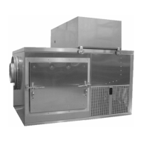
Figure A-2 - Pressure Switches
Low Pressure
Switch
High Pressure
Switch
High Pressure
Reset
Figure A-4 – Low Water
Safety Float Switch
Figure A-3 – Low Water
Safety Float Switch
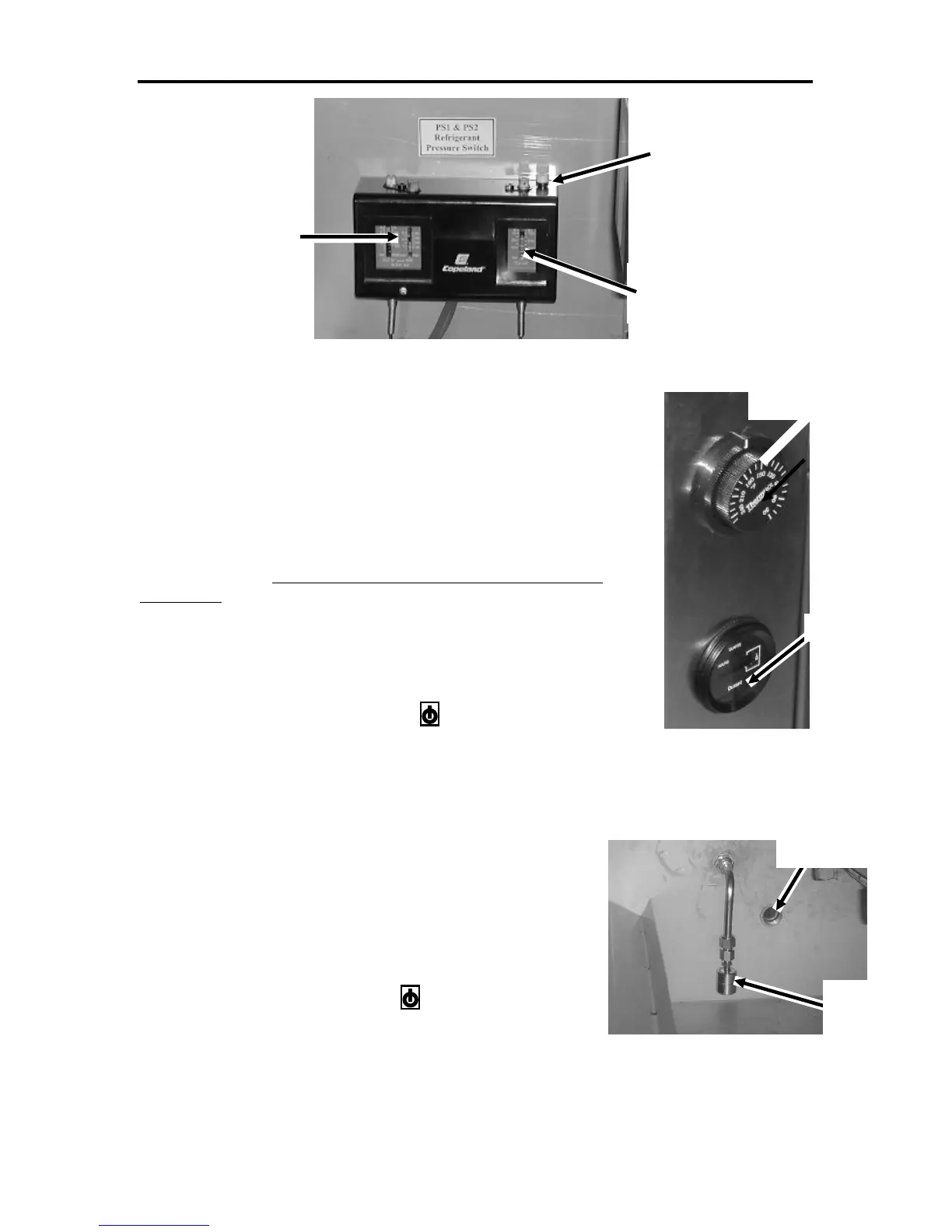
UV Time
Air Temperature
Safety Thermostat
Low Water
Safety Float
Condensate
Drain