Step 3 is the reverse of step 1. Solenoid #1 is energized, providing control air to and opening the left
exhaust valve.
Solenoid #2 is energized, providing control air to and closing the left inlet valve. Solenoid #3 and #4 are de-
energized. Thus the right inlet is open, and the right exhaust is closed. All the wet air is now flowing
through the right tower and is being dried at line pressure. The left tower is being regenerated at
atmospheric pressure. Solenoid #5 is de- energized and closed.
STEP 4 - LEFT REPRESSURIZING, RIGHT DRYING Step 4 is the reverse of Step 2. Solenoid #1 de-
energizes, allowing the left exhaust valve to close and allowing the dryer to repressurize. In addition,
Solenoid #5 energizes providing additional air for repressurization.
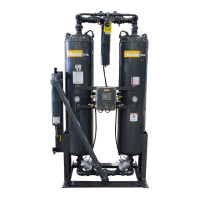
NOTE: The Purge Gauge (middle) should read purge pressure, except during repressurization. Purge
flow is calculated by the Purge Formula in this manual and by checking the proper graph. Purge
pressure for standard inlet design conditions is listed on page 1. For other than standard or design
conditions use the purge formula and charts for purge flow/pressure calculation, or consult the factory.
 Loading...