Pilot Operated Prop. DC Valve with VCD
®
Series D*1FP/FE Explosion Proof
Operation Manual
21
Parker Hannifin Corporation
MSG11-5715-718 D_1FP IECEX UK.indd 19.12.19
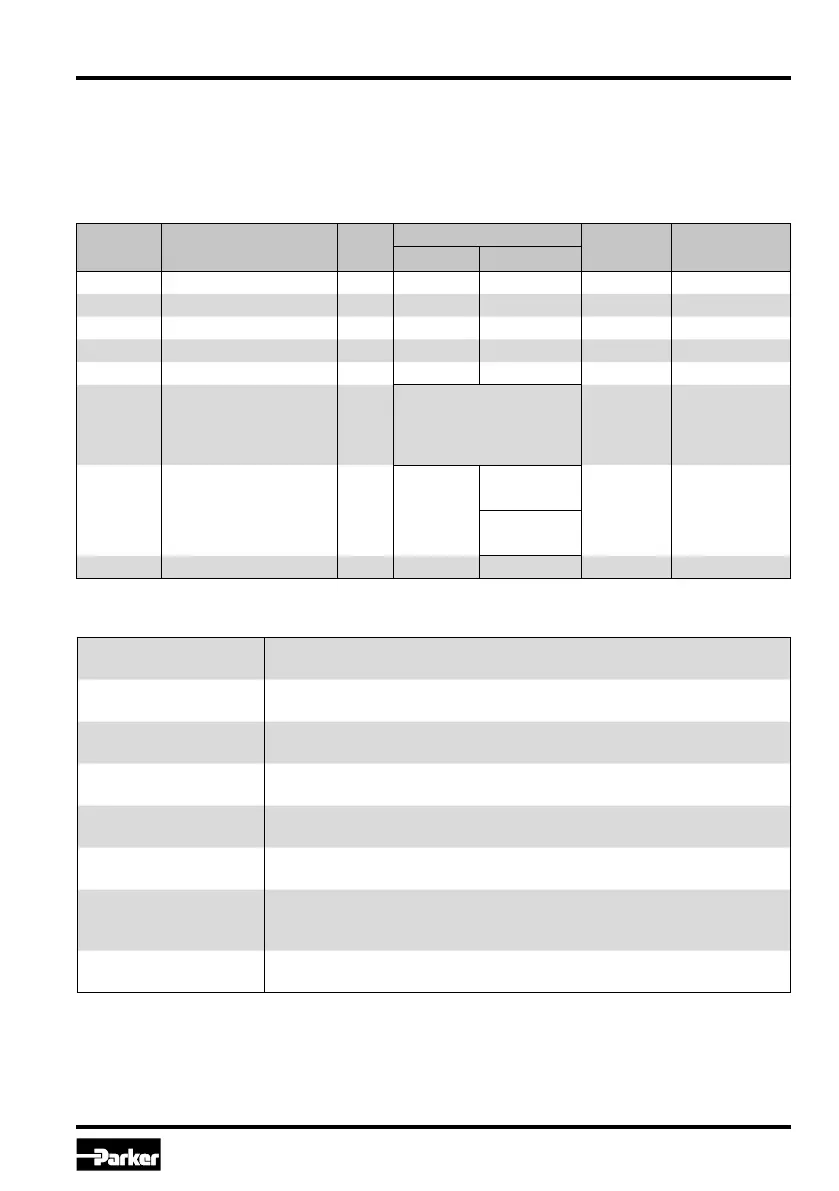
P1
Adjustment of zero position shifting (offset).
To compensate for unbalances.
P3
MAX +
Adjustment of maximum signal span for positive output signal.
To match the command signal span to the valve operating range.
P4
MAX -
Adjustment of maximum signal span for negative output signal.
To match the command signal span to the valve operating range.
P7
MIN +
Adjustment of stroke step for valve side A at min. operating threshold.
To compensate for the overlap of the valve spool.
P8
MIN -
Adjustment of stroke step for valve side B at min. operating threshold.
To compensate for the overlap of the valve spool.
E17
option command
Adjustment of the command signal option.
To match the command signal input to the input signal mode.
E19
cable break detection
command
Adjustment of the operating mode for the command cable break
detection. To turn on resp. off of the cable break detection of the
command signal at a selected command signal option of 4...20 mA.
E25
operating threshold
Adjustment of the MIN operating threshold.
To match the response sensitivity for the MIN-stroke step.
Individual description of basic parameters
Parameter overview for basic mode
Parameter Description Unit
Parameter Range Default
Setting
Comment
from up to
P1 Zero adjust % -90.0 90 0.0
P3 MAX channel A % 50.0 100.0 100.0
P4 MAX channel B % 50.0 100.0 100.0
P7 MIN channel A % 0.0 50.0 0.0
P8 MIN channel B % 0.0 50.0 0.0
E17 option command –
1 = ±10 V
2 = ±20 mA
3 = 4-20 mA
5 = ±10 mA
1 = ±10 V
only displayed,
not adjustable
E19
cable break detection
command
– 0
0 (±10 V /
±20 mA)
0/1
code S0 only,
only displayed,
not adjustable
1 (4...20 mA)
E25 MIN operating threshold 0.01 % 50 200 100
Adjustment parameters
The available parameters may be divided into
multiple groups and are characterized by different
letters:
P-parameters operating parameters
E-parameters advanced parameters
J-parameters

 Loading...


