52
Gemini GT Hardware Installation Guide
Standards
UL, cUL 508C
CE for LVD 72/23/EEC
BS EN61010-1:1993/A2:1995 (ie includes 1995 amendment AMD 8961)
Safety requirements for electrical equipment for measurement, control,
and laboratory use Part 1. General requirements
CE for EMC 89/336/EEC
BS EN61800-3: 1997 Adjustable speed electric power drive systems
Part 3. EMC product standard including
specific test methods.
IEC 61800-3: 1996 Adjustable speed electric power drive systems
Part 3. EMC product standard including
specific test methods.
Inputs and Outputs
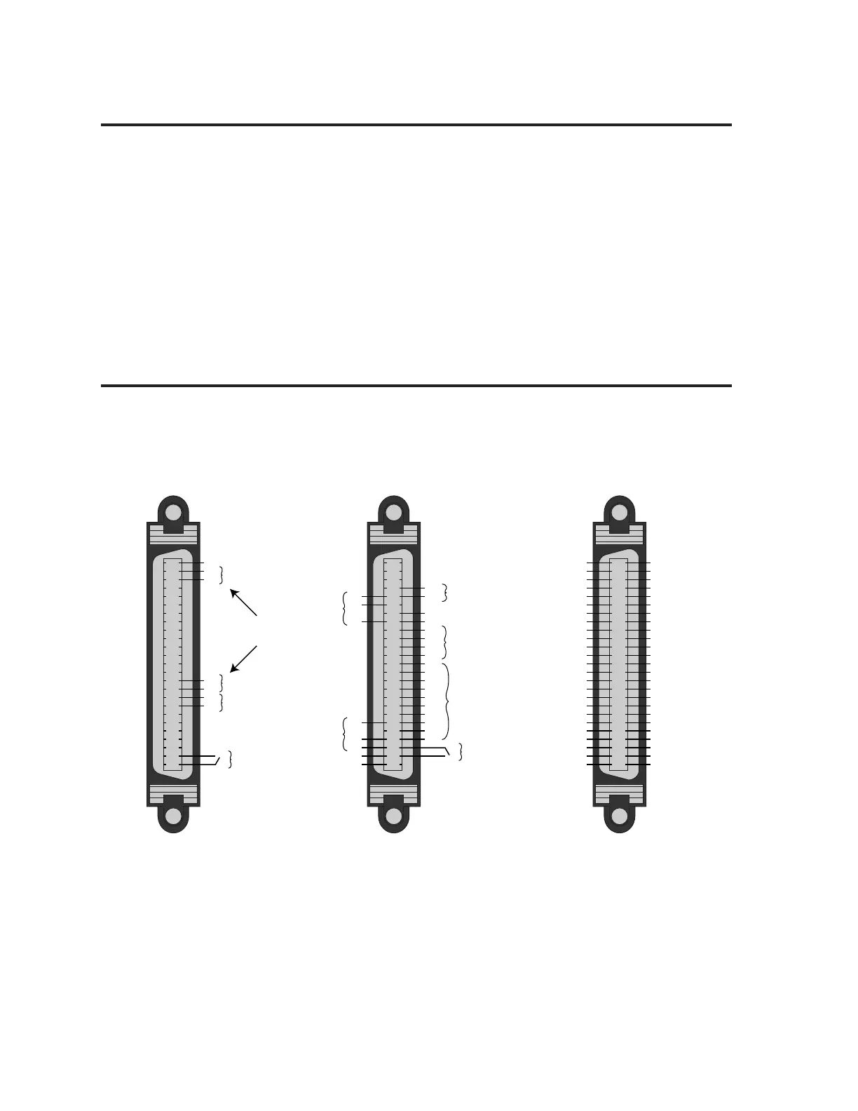
This section describes all inputs and outputs (I/O) located on the 50 pin
DRIVE I/O connector. Not all are required for your system to operate. The next
drawing summarizes which are required, and which are optional.
Optional Complete Pinout
reserved
reserved
reserved
Output Ground
Output 4
Output 3
Output Ground
Output 2
Output Ground
reserved
Input Ground
reserved
reserved
reserved
Input Ground
reserved
reserved
reserved
Input Ground
Input 3
Input Ground
Input 2
Input 1
CNTRL-P
VINref
Analog Ground
±10V Vel Cmd—
±10V Vel Cmd+
Analog Output B
Analog Output A
Digital Ground
reserved
reserved
Direction– Out
Direction+ Out
Step– Out
Step+ Out
ZX–
ZX+
Dir-/CCW-/BX–
Dir+/CCW+/BX+
Step-/CW-/AX–
Step+/CW+/AX+
Digital Ground
Digital Ground
Encoder +5V
Encoder +5V
Reset
Digital Ground
Enable
25
24
23
22
21
20
19
18
17
16
15
14
13
12
11
10
9
8
7
6
5
4
3
2
1
25
24
23
22
21
20
19
18
17
16
15
14
13
12
11
10
9
8
7
6
5
4
3
2
1
50
49
48
47
46
45
44
43
42
41
40
39
38
37
36
35
34
33
32
31
30
29
28
27
26
22
21
17
14
13
4
3
2CNTRL-P
VINref
Inputs
Outputs
46
45
43
31
29
28
27
26
Analog
Outputs (2)
Step/Dir Out
Encoder In
Reset
Required
±10V Velocity Cmd—
±10V Velocity Cmd+
Dir-/CCW-/BX–
Dir+/CCW+/BX+
Step-/CW-/AX–
Step+/CW+/AX+
Enable
25
24
23
11
10
9
8
2
1
Choose one
Input mode
Drive I/O Connector
Connector specifications are:
Mating Connector*
Gemini Drive: (not provided; see note):
Manufacturer: AMP AMP
Connector Type: CHAMP .050 Series II CHAMP .050 Series II
AMP Part Number: 2-178238-7 2-175677-7
Wire Gauge: not applicable use 28 AWG (0.08 mm
2
)
* Note: Mating connectors are not provided with Gemini drives; Compumotor cables are
available with mating connectors attached. If you make your own cables, you must use a
“jack screw” style fastener, not “spring clip” style. For connector integrity, we recommend
you use AMP brand connectors.
Artisan Technology Group - Quality Instrumentation ... Guaranteed | (888) 88-SOURCE | www.artisantg.com

 Loading...


