Appendix A – Specifications
53
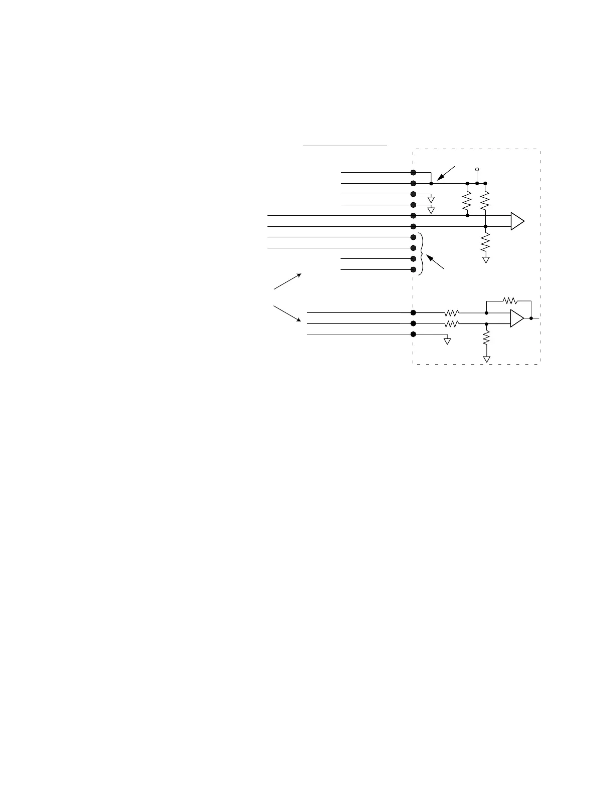
Command Input (required)
The Gemini drive can accept several types of command input signals. Use the
DMODE command to configure your drive to accept either a pulse input (step/
direction, clockwise/counterclockwise, or encoder), or ±10V velocity command.
681Ω
Internal Connections
681Ω
681Ω
Same circuit as Step+/Step-
Configure drive
either for pulse input
or for
±
10V velocity
command input
Vel. Command+ (±10V)
Vel. Command– (±10V)
Analog Ground
DRIVE I/O Connector
+5V
95KΩ
95KΩ
20KΩ
20KΩ
250 mA
maximum source
Encoder +5
Encoder +5
Digital Ground
Digital Ground
Encoder A+
Encoder A–
Encoder B+
Encoder B–
Encoder Z+
Encoder Z-
23
24
25
Step+
Step-
Dir+
Dir-
CW+
CW-
CCW+
CCW-
4
5
6
7
8
9
10
11
12
13
Command Inputs
If you use a pulse source to generate step/direction, CW/CCW or encoder tracking
signals, note that the drive’s pulse inputs use differential receivers without opto-
couplers. For best performance, follow these instructions:
Connection Instructions for Pulse inputs
1. Connect your control’s logic ground to the Gemini’s ground, pin 6 or 7. This
connection ensures that the signals stay within the common mode range of the
differential receivers, and must not be omitted.
2. If you use a Compumotor 6K Controller, use the step and direction command cable.
See
Cable Specifications
later in this appendix for part numbers.
If you use ±10V velocity command input signals, follow these instructions:
Connection Instructions for ±10V Velocity Command Inputs
1. Connect COMMAND+ to pin 23.
2. Connect COMMAND- to pin 24.
3. Connect your controller’s analog ground reference to pin 25.
4. Use the flying lead cable to connect the 50 pin DRIVE I/O connector to your
controller. See
Cable Specifications
later in this appendix for part numbers.
Artisan Technology Group - Quality Instrumentation ... Guaranteed | (888) 88-SOURCE | www.artisantg.com

 Loading...


