14
Proportional Pressure Valves
Series RE*T / R*V
Operation Manual
Parker Hannifin Corporation
RE_-R_V obe_24-45-A-B 5715-651 UK 29.01.19
Electrical Connection
The electrical connection of the valve takes place
by one common cable, which is coupled to the
integrated electronic driver by a central connector
assembly.
The connection requires a 6 + PE female connector
EN 175201-804.
The female connector has to be ordered
separately under article nr. 5004072.
A female connector with metal housing is
required! Plastic made models may create
function problems due to insufficient EMC-
characteristics.
The connecting cable has to comply to the following
specification:
Cable type control cable, flexible,
7 conductors, overall braid
shield
Cross section min. AWG16/1.0 mm
2
Outer dimension 8...12 mm
Cable length max. 50 m
For cable lengths > 50 m consult factory.
The connection cable is coupled to the female
connector by solder joints.
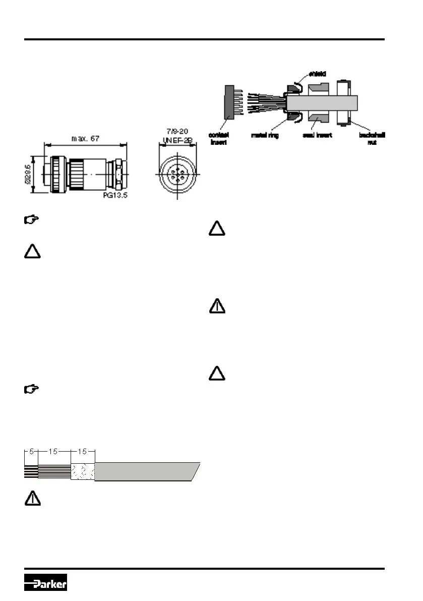
Skinning lengths for the connecting cable:
The shielding has to be assembled according the
outline below:
The backshell nut of the cable gland has to be
tighten with a suitable tool. The target value for the
tightening torque is 4 Nm. Tighten the cap nut with
a torque of approx. 5 Nm after attaching the female
connector on the socket outlet.
Incomplete tightening of backshell nut resp.
cap nut may result in automatic release of
the connection as well as degradation of the
water tightness.
Follow the “instructions for use“ for installation
of female connectors made by other kind of
brands!
The cable connection to the female connector
has to take place by qualified personnel! A
short between individual conductors resp. to
the connector housing , bad soldering as well
as improper shield connection may result in
malfunction and breakdown of the valve.
The mounting surface of the valve has to be
tied to the earth grounded machine frame. The
earth ground wire from the valve connecting
cable as well as the cable shield have to be
tied to the protective earth terminal within the
control unit. It is necessary to use a low ohmic
potential connection between control unit and
machine frame to prevent earth loops (cross
section AWG 6).
Do not disconnect cable socket under tensi-
on!

 Loading...


